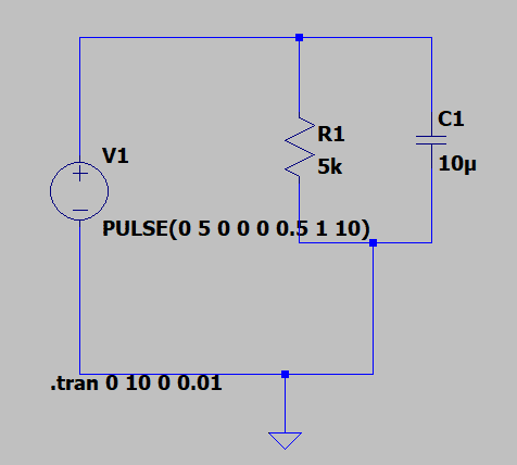
As others have pointed out, the the real world, there will always be some series resistance.
But I think it's also important to understand the world of networks with idealized components. Every schematic is wrong, schematics are a simplification of the incredibly complex world of electricity and magnetism. There is an art to modeling, or communication with other EEs, with schematics; i.e. what you choose to show and what you choose to leave out. Sometimes a wire with 2mΩ of resistance can be ignored, other times it's really important.
When you start modeling circuits with ideal components there are somethings that don't make sense. When you do the math there is no answer, or you get infinite results. Here are a couple of things to look out for:
1) Any loop in a network that contains only voltage sources and capacitors. Except for the trivial case where the initial conditions match perfectly and the voltage source waveforms are smooth*. This will result in infinite currents in the solution. This is a sign that you need to include some series resistance in that loop to remove the infinities.
2) The dual case: Any node in a network that connects only current sources and inductors. Except for the trivial case where the initial conditions match perfectly and the current source waveforms are smooth*. This will result in infinite voltages in the solution. This is a sign that you need to include some shunt resistance at that node to remove the infinities.
This is why
@berkeman was surprised that LTSpice would let you do this. Your circuit is an idealized model that doesn't make sense. It's why experienced EEs immediately respond with comments about the model accuracy and not about the results.
*By smooth I mean the 1
st derivative (the slope) is always finite.