Fracture Toughness
- 5
- 0
- TL;DR Summary
- Cracked carbon graphite seal that is used in an inline axial piston, variable displacement hydraulic pump.
We have a molded carbon graphite seal that is used in an inline axial piston, variable displacement hydraulic pump. One of our customers reported that, when using the “A” parts in the past, they only needed to replace them due to normal wear. However, after switching to our parts, the replacement cycle seems to be much shorter due to “broken” or “cracked” failures. This issue was identified after hydraulic fluid leakage was observed. According to their records, the same problem has occurred three times over the past few years. We have sold over 1,000 parts to a dozen customers, and this is the only customer that has reported cracking issues. It is unclear whether this is a quality escape on our side or something happening at the customer’s end, but my first goal is to determine the root cause of the cracks.
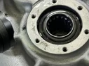
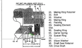
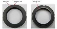
Based on the photos provided, two of the failed seals show cracks initiating from the root of the fillet radius. You can see the tang of the seal retainer engaging with the anti-rotation slots. The shaft seal subassembly is held in position by the seal retainer, which is attached to the mounting flange with fasteners. To me, it appears the cracks may have been caused by some type of impact. Both components are static relative to the shaft, so neither should be rotating. Could vibration be the cause?
We performed a material analysis on the cracked parts, and no deviations were found. Hardness, density, microstructure, and porosity were checked and compared against the A seal, and the results were equivalent. On the drawing, the ID, OD, slot-to-slot distances, slot width, and fillet radius also show no significant differences compared to the A seal. However, we only performed a 1.5 AQL inspection on this part, and slot-to-slot distance was not measured, so I cannot rule out a quality escape. That said, since this is a molded product, the process should be highly repeatable.
Another possibility is that something went wrong during installation on the customer’s side. But since the A seal did not experience the same issue, I am inclined to believe the root cause may still be on our end.
Pump General Characteristics:
- Type: Inline axial piston pump
- Displacement: Variable
- Rotation Direction: Clockwise (viewed from the coupling shaft end)
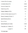
Performance Ratings
- Maximum Continuous Operating Pressure: 209.0 bar (3031 psig)
- Rated Speed: 3750 rpm
- Maximum Continuous Speed: 4000 rpm
Installation Data
- Hydraulic Fluid:
- Alkyl Phosphate Ester
- Fluid Temperature Range:
- -45 °C to +121 °C (-50 °F to 250 °F)
- System Filtration:
- 10 µm (400 µin) nominal
- 25 µm (1000 µin) absolute