Which of these rods are in equilibrium?

  • #1
ymnoklan
68
4
Homework Statement
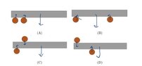
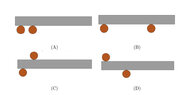
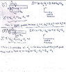
A rod with a square cross-section is imagined to be supported by two smooth cylinders in four different ways (see figure). Draw all the forces acting on the rod in each case, and use what you know about equilibrium and torque to assess whether it is possible to keep the rod supported in each of these four configurations.
Relevant Equations
Sigma F = 0, Sigma tau = 0, tau = F*r*sin(theta), G = m*g
(My attempt of drawing the forces is the figure with the arrows). Intuitively I would say that non of the rods are supported in any of these configurations, but I struggle to give a good explanation for why. I could guess that B would be able to keep up, however summing the forces, it seems just as unbalanced as A (which obviously can’t be supported). What have I misunderstood/overlooked?
 

Attachments

  • IMG_2745.jpeg
    IMG_2745.jpeg
    12.6 KB · Views: 4
  • IMG_2744.jpeg
    IMG_2744.jpeg
    10 KB · Views: 3
Physics news on Phys.org
  • #2
ymnoklan said:
I could guess that B would be able to keep up, however summing the forces, it seems just as unbalanced as A
You are not given the magnitudes, so how can you sum them?
 
  • #3
True. How am I supposed to solve this?
 
  • #4
You are saying that (A) is obviously not balanced and I agree. Can you express mathematically why? This should give you a clue about how to deal with the less obvious cases.
 
  • #5
kuruman said:
You are saying that (A) is obviously not balanced and I agree. Can you express mathematically why? This should give you a clue about how to deal with the less obvious cases.
 

Attachments

  • IMG_2753.jpeg
    IMG_2753.jpeg
    81.4 KB · Views: 3
  • #6
kuruman said:
You are saying that (A) is obviously not balanced and I agree. Can you express mathematically why? This should give you a clue about how to deal with the less obvious cases.
In B x>d, which indicates that the rod is supported
 
  • #7
ymnoklan said:
In B x>d, which indicates that the rod is supported
Good. What about the other two cases?

Please note that we prefer that you post your work in ##\LaTeX## which makes the equations more legible and easier to refer to. To learn how, please click on the link "LaTeX Guide", lower left abpve "Attach files." If you must post photos of your work until you become proficient in LaTeX, please avoid using square-ruled paper which makes your handwriting hard to read. Thank you.
 
  • #8
kuruman said:
Good. What about the other two cases?

Please note that we prefer that you post your work in ##\LaTeX## which makes the equations more legible and easier to refer to. To learn how, please click on the link "LaTeX Guide", lower left abpve "Attach files." If you must post photos of your work until you become proficient in LaTeX, please avoid using square-ruled paper which makes your handwriting hard to read. Thank you.
I don't think neither C nor D are supported as only the cylinder below the rod can exert an upward normal force. This cannot balance both force and torque.
Also, thank you for the feedback. I will do my best.
 
  • #9
ymnoklan said:
I don't think neither C nor D are supported as only the cylinder below the rod can exert an upward normal force. This cannot balance both force and torque.
To guide your thinking (and the math) for (C) and (D) imagine that the top cylinder is a coin, the rod is a ruler and the bottom cylinder is your extended index finger. Your task is to balance the ruler + coin on your finger like a see-saw. Which of the two choices (if any) is more likely to work? Then put in the math to find the conditions for success or failure.
 
  • #10
ymnoklan said:
I don't think neither C nor D are supported as only the cylinder below the rod can exert an upward normal force.
If it is not balanced, there must be a way the rod's mass centre can move downwards without either cylinder moving. In D, if the mass centre moves down then either the left end of the rod must move up or everywhere left of the mass centre must move down.
ymnoklan said:
This cannot balance both force and torque.
It is not necessary for the cylinder below to do everything. The cylinder above can help. We only need that the net force from the cylinders is upwards, balancing the weight of the rod, and the net torque from the rods about the mass centre is zero.
 
  • #11
kuruman said:
To guide your thinking (and the math) for (C) and (D) imagine that the top cylinder is a coin, the rod is a ruler and the bottom cylinder is your extended index finger. Your task is to balance the ruler + coin on your finger like a see-saw. Which of the two choices (if any) is more likely to work? Then put in the math to find the conditions for success or failure.
Thank you for the hint! Well, D is obviously a more likely candidate to work as the top cylinder changes the center of mass of the system towards the left. I really struggle with the math though.
 
  • #12
haruspex said:
If it is not balanced, there must be a way the rod's mass centre can move downwards without either cylinder moving. In D, if the mass centre moves down then either the left end of the rod must move up or everywhere left of the mass centre must move down.

It is not necessary for the cylinder below to do everything. The cylinder above can help. We only need that the net force from the cylinders is upwards, balancing the weight of the rod, and the net torque from the rods about the mass centre is zero.
Here is my attempt at the math
 

Attachments

  • IMG_2758.jpeg
    IMG_2758.jpeg
    40.5 KB · Views: 2
  • #13
Your answers in (C) and (D) can be made mathematically simpler if you choose a different point about which you calculate torques. Note that if the sum of the torques is zero about one point, it is zero about all points. The rod is not going to suddenly accelerate if you change the reference point for the torques. So you might as well choose a convenient point which is usually the point about which the system will rotate if it is NOT in equilibrium. When the center of mass (CM) is directly above the reference point, the system will be in equilibrium in cases where gravity is the only external force acting.

The CM of the (top cylinder + rod) system is at a point between the midpoint of the rod and the top cylinder. Thus, the picture in (C) cannot work while the picture in (D) can.

In (C) and (D) the convenient reference point for torques, i.e. the pivot, is the cylinder below the rod. You might wish to redo the math with the reference point at the pivot to see how this makes the mathematical explanation easier and to find the equilibrium condition for (D).
 
  • Like
Likes Lnewqban
  • #14
kuruman said:
Your answers in (C) and (D) can be made mathematically simpler if you choose a different point about which you calculate torques. Note that if the sum of the torques is zero about one point, it is zero about all points. The rod is not going to suddenly accelerate if you change the reference point for the torques. So you might as well choose a convenient point which is usually the point about which the system will rotate if it is NOT in equilibrium. When the center of mass (CM) is directly above the reference point, the system will be in equilibrium in cases where gravity is the only external force acting.

The CM of the (top cylinder + rod) system is at a point between the midpoint of the rod and the top cylinder. Thus, the picture in (C) cannot work while the picture in (D) can.

In (C) and (D) the convenient reference point for torques, i.e. the pivot, is the cylinder below the rod. You might wish to redo the math with the reference point at the pivot to see how this makes the mathematical explanation easier and to find the equilibrium condition for (D).
Hm, I thought had chosen the bottom cylinder as my pivot point in configuration C already. In D, I did chose the top cylinder as pivot point indeed, but when I try to switch it, the math doesn’t look any simpler. Instead I get a situation where I can’t tell whether d1 or d2 is larger (or equal in size). Well, I guess the equilibrium condition for (D) is d2>d1, or do you mean something else? What have I done wrong?
 
  • #15
Maybe simple, qualitative (without any maths) answers would suffice.

For example, for part A), here is a possible answer:

1736447126843.png

##F_A## and ##W## produce clockwise torques about B. ##F_B## produces zero torque about B. Therefore there will be a net clockwise torque about B. Consequently the bar will rotate about B and fall. I.e. the rod isn't supported.
 
  • #16
The distance between cylinder 1 and the center of mass is irrelevant for the purposes of calculating torques. You need to find what mathematical condition must be satisfied for the distance between the CM and the pivot to be zero. The relevant distances are the lever arms, i.e. the distances ##d_1## and ##d_2## from the pivot to the point of application of the force of gravity. See drawings below for (C) and (D). Then setting the net torque equal to zero, should give you an expression that you can solve to find the needed mathematical condition.
Cylinder pivot_C.png
Cylinder pivot.png
 
  • #17
ymnoklan said:
Here is my attempt at the math
Your diagram for D in post #12 has the mass centre between the two rods. This does not match the given diagram in post #1.
Steve4Physics said:
Maybe simple, qualitative (without any maths) answers would suffice.
I'm sure that was the intent of the question, but I suggested doing the algebra because @ymnoklan couldn’t see how balance would be achieved in any of the cases.
 
  • Like
Likes ymnoklan and Steve4Physics
  • #18
kuruman said:
The distance between cylinder 1 and the center of mass is irrelevant for the purposes of calculating torques. You need to find what mathematical condition must be satisfied for the distance between the CM and the pivot to be zero. The relevant distances are the lever arms, i.e. the distances ##d_1## and ##d_2## from the pivot to the point of application of the force of gravity. See drawings below for (C) and (D). Then setting the net torque equal to zero, should give you an expression that you can solve to find the needed mathematical condition.
View attachment 355592View attachment 355593
Thank you! Those figures were incredibly helpful. What do you think if this solution then? (I know it is probably possible to simplify the mathematical condition further, however I am not sure how?)
 

Attachments

  • IMG_2760.jpg
    IMG_2760.jpg
    44.8 KB · Views: 1
  • #19
Steve4Physics said:
Maybe simple, qualitative (without any maths) answers would suffice.

For example, for part A), here is a possible answer:

View attachment 355576
##F_A## and ##W## produce clockwise torques about B. ##F_B## produces zero torque about B. Therefore there will be a net clockwise torque about B. Consequently the bar will rotate about B and fall. I.e. the rod isn't supported.
Thank you for the figure! This is what actually got me to get an intuition of the situation, but yes, I would prefer to solve it mathematically
 
  • Like
Likes Steve4Physics
  • #20
ymnoklan said:
Thank you! Those figures were incredibly helpful. What do you think if this solution then? (I know it is probably possible to simplify the mathematical condition further, however I am not sure how?)
Your algebra is right, and you correctly conclude that D could be stable, but that is not the same as showing it is stable. Can you think of a way to show that?
 
  • #21
haruspex said:
Your algebra is right, and you correctly conclude that D could be stable, but that is not the same as showing it is stable. Can you think of a way to show that?
Do you mean by perturbation analysis?
 
  • #22
ymnoklan said:
Do you mean by perturbation analysis?
By whatever means, but perhaps reasoning as in the first half of my post #10.
 
  • #23
@ymnoklan equations and text inside images, as in your post #5, are not allowed here. Please post text and equations directly, using the PF LaTeX feature for equations. There is a LaTeX Guide link at the bottom left of the text box you use to post.
 
  • #24
haruspex said:
By whatever means, but perhaps reasoning as in the first half of my post #10.
I thought showing that the sum of forces and the sum of rotational momentum both equal zero would indicate that the system is stable. Is this wrong? What else is required?
 
  • #25
ymnoklan said:
I thought showing that the sum of forces and the sum of rotational momentum both equal zero would indicate that the system is stable.
It would, but you only showed the sums could be zero. The sums being zero requires the normal forces to take certain values. Why do they take those values?
 
  • #26
haruspex said:
It would, but you only showed the sums could be zero. The sums being zero requires the normal forces to take certain values. Why do they take those values?
Okay, if I solve for N then? This gives me N = (d_2 - d_1)/d_2 which must be greater than zero (because the normal force cannot be negative/downward). This gives the condition d_2>d_1.
 
  • #27
ymnoklan said:
Okay, if I solve for N then? This gives me N = (d_2 - d_1)/d_2 which must be greater than zero (because the normal force cannot be negative/downward). This gives the condition d_2>d_1.
No, that still only says there exist values for the normal forces which put the system in equilibrium.
Consider a simpler question. Place a block weight W on the floor. It sits in equilibrium because the normal force from the floor is also W, but upwards. Why is the normal force that value?
 
  • #28
haruspex said:
No, that still only says there exist values for the normal forces which put the system in equilibrium.
Consider a simpler question. Place a block weight W on the floor. It sits in equilibrium because the normal force from the floor is also W, but upwards. Why is the normal force that value?
Because it balances the weight - the sum of forces is zero?
 
  • #29
ymnoklan said:
Because it balances the weight - the sum of forces is zero?
But why does it match the weight? Why isn't it a bit more or a bit less? Think about what would happen.
 
  • #30
haruspex said:
But why does it match the weight? Why isn't it a bit more or a bit less? Think about what would happen.
I don’t think I get what you mean. Could you give me a hint? I mean if the sum of the forces weren’t zero, the system would accelerate, which is NOT what we want here
 
  • #31
ymnoklan said:
I don’t think I get what you mean. Could you give me a hint? I mean if the sum of the forces weren’t zero, the system would accelerate, which is NOT what we want here
If the normal forces from the floor were to exceed the weight the block would rise, yes? What physical law says a block placed gently on the floor won’t, in general, rise off it?

What if it were less than the weight?
 
  • #32
haruspex said:
If the normal forces from the floor were to exceed the weight the block would rise, yes? What physical law says a block placed gently on the floor won’t, in general, rise off it?

What if it were less than the weight?
Newton’s first law says that the sum of the forces must be zero (as it is at rest). Newton’s second law says that the acceleration must be zero (as it is not accelerating) and Newton’s third law says that the opposite reaction to the block’s weight (the normal force from the floor to the block), must be equal in size (but upwards).
If the normal force was less than the weight, the block would sink through the floor.
Is this what you mean? Or have I misunderstood something again?
 
  • #33
ymnoklan said:
Newton’s first law says that the sum of the forces must be zero (as it is at rest).
But why is at rest? You cannot use the fact that the sum of forces is zero because you are using its being at rest to prove that, so your argument becomes circular.
ymnoklan said:
Newton’s third law says that the opposite reaction to the block’s weight (the normal force from the floor to the block), must be equal in size (but upwards).
Newton III says the force the block exerts on the floor and the force the floor exerts on the block are equal and opposite. It does not say the weight of the block (the force gravity exerts on the block) equals either of these.
ymnoklan said:
If the normal force was less than the weight, the block would sink through the floor.
Right. Indeed, if the floor were liquid water that would happen. So why doesn’t it happen with a stone or wooden floor? What is different?
It might help to think in a bit more detail about the process. All solid bodies have some springiness. Suppose you were to hold the block so that it is just touching the floor, no forces yet, then let go. It will descend a tiny bit, compressing the surfaces of both floor and block, but soon stops. How were the forces changing as it was making that descent?
 
  • #34
haruspex said:
But why is at rest? You cannot use the fact that the sum of forces is zero because you are using its being at rest to prove that, so your argument becomes circular.
I'm confused. Doesn't the sum of forces HAVE to be zero if the box is at rest?
haruspex said:
Newton III says the force the block exerts on the floor and the force the floor exerts on the block are equal and opposite. It does not say the weight of the block (the force gravity exerts on the block) equals either of these.
Good point. Thank you for pointing this out.
haruspex said:
Right. Indeed, if the floor were liquid water that would happen. So why doesn’t it happen with a stone or wooden floor? What is different?
The solid is rigid compared to the liquid? While water flows and is easily deformed (because the molecules are not held in fixed positions), the solid is made up of molecules that are held tightly together in a fixed structure. I don't think this is what you are hinting to though.
 
  • #35
ymnoklan said:
I'm confused. Doesn't the sum of forces HAVE to be zero if the box is at rest?
Yes, it is at rest if and only if the forces are in balance, but you cannot use that to prove one is true unless you have first proved the other is true by some other means. Otherwise you could apply that to the block on water case and say that should be at rest too.
ymnoklan said:
The solid is rigid compared to the liquid?
Right.
The block pressing on the floor deforms it. The floor, being rigid, resists deformation and develops an increasing resistance until it is sufficient to prevent further ingress of the block.
In short, we can define the normal force that rigid bodies exert on each other as the minimum force required to prevent interpenetration.
Applying this to case D, it should be clear that if the mass centre of the rod descends significantly then something has to give: bend, break or be crushed. You could make that rigorous through geometry; no need to analyse forces and torques.
This is is the argument I was hinting at in post #10.
 
Back
Top