Effect
- 13
- 0
I want to understand how this circuit demonstrating the photoelectric effect works. Please see attached picture.
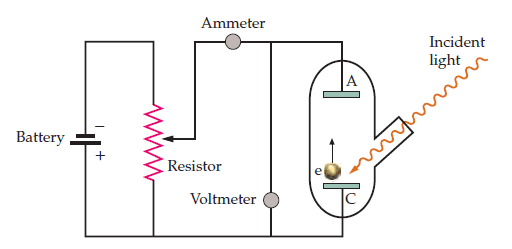
On the picture we see light entering the cathode C, which, if the light is above the threshold frequency can eject electrons from the cathode, which hits the anode A, creating a (conventional) current flowing from A to C. This current can be measured in the Ammeter and the voltage can be measured in the Voltmeter. Then we can connect a battery, where we can put in a "retarding voltage". The retarding voltage can then be increased until the current between A and C becomes zero. From this point on and for higher retarding voltage the electrons with the most kinetic energy don't have enough energy to make it through from C to A anymore. So if we for example know that the maximum kinetic energy of the electrons is 1.5 eV, then this will happen when the retarding voltage is increased to 1,5 V. Correct so far?
So then, I think the only thing I don't understand about this circuit is why there is a potentiometer in it. I understand it's to regulate the voltage from the battery, as I described above, but it seems unnecessary to use a potentiometer for that. Wouldn't it make more sense to just have a variable resistor?
On the picture we see light entering the cathode C, which, if the light is above the threshold frequency can eject electrons from the cathode, which hits the anode A, creating a (conventional) current flowing from A to C. This current can be measured in the Ammeter and the voltage can be measured in the Voltmeter. Then we can connect a battery, where we can put in a "retarding voltage". The retarding voltage can then be increased until the current between A and C becomes zero. From this point on and for higher retarding voltage the electrons with the most kinetic energy don't have enough energy to make it through from C to A anymore. So if we for example know that the maximum kinetic energy of the electrons is 1.5 eV, then this will happen when the retarding voltage is increased to 1,5 V. Correct so far?
So then, I think the only thing I don't understand about this circuit is why there is a potentiometer in it. I understand it's to regulate the voltage from the battery, as I described above, but it seems unnecessary to use a potentiometer for that. Wouldn't it make more sense to just have a variable resistor?
Attachments
