Discussion Overview
The discussion revolves around the relative trajectories of movement concerning a rotating circle and a stationary point A. Participants explore the implications of different motions, including the rotation of the circle and the rotation of point A, and how these affect the perceived positions of points on the circle. The scope includes conceptual reasoning and technical clarification regarding the geometry of motion and its implications in a physical context.
Discussion Character
- Exploratory
- Technical explanation
- Conceptual clarification
- Debate/contested
Main Points Raised
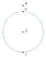
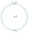
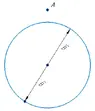
- Some participants propose that the rotation of a circle regarding point A and the rotation of point A regarding the circle yield different relative trajectories.
- Others argue that the diagrams provided lack clarity and sufficient labeling, making it difficult to understand the relationships between the elements depicted.
- A participant describes two scenarios: one where point A is stationary while the circle rotates, and another where the circle is stationary and point A rotates, questioning whether this understanding is correct.
- There is a discussion about the ambiguity of terms like "to the right" and the importance of specifying perspectives when describing movements.
- Some participants highlight the need for consistency in descriptions, especially regarding the orientation of points and observers during the motion.
- A later reply introduces the concept of electric and magnetic fields in relation to the movement of points B and C, suggesting that the charge distribution on the circle's surface is affected by the type of motion.
- Concerns are raised about whether the reasoning regarding the equivalence of movements is valid, particularly in relation to the observer's orientation.
Areas of Agreement / Disagreement
Participants express differing views on the clarity of the diagrams and the implications of the movements described. There is no consensus on whether the reasoning regarding the equivalence of movements is correct, and the discussion remains unresolved regarding the interpretation of the scenarios presented.
Contextual Notes
Limitations include potential ambiguities in the descriptions of motion and perspective, as well as the need for clearer labeling of diagrams to facilitate understanding. The discussion also touches on the application of these concepts to electric and magnetic fields, which introduces additional complexity.
Who May Find This Useful
This discussion may be of interest to those studying geometry, physics, or engineering, particularly in the context of motion and field interactions.