Analyzing a frequency-mixer circuit in LTSpice

  • Thread starter Thread starter minhha04
  • Start date Start date
  • Tags Tags
    Circuit Ltspice
Click For Summary
SUMMARY

This discussion focuses on troubleshooting a frequency-mixer circuit analysis in LTSpice. The user encountered issues with transient analysis at 100 microseconds, where the voltage at IFF displayed a straight line instead of reaching a steady-state value. The problem was identified as a misinterpretation of frequency notation, where "M" was mistakenly read as millihertz instead of megahertz. Correcting the frequency notation to "MEG" resolved the issue, allowing the analysis to proceed successfully.

PREREQUISITES
  • Understanding of LTSpice simulation software
  • Knowledge of frequency mixer circuit design
  • Familiarity with transient analysis techniques
  • Basic concepts of large signal and small signal analysis
NEXT STEPS
  • Learn about LTSpice frequency notation and SI prefixes
  • Explore large signal transient simulation techniques in LTSpice
  • Study the mathematical principles behind frequency mixing
  • Investigate common pitfalls in SPICE simulations and how to avoid them
USEFUL FOR

Electronics engineers, circuit designers, and students working with LTSpice for frequency mixer circuit analysis will benefit from this discussion.

minhha04
Messages
2
Reaction score
1
Summary:: I'm trying to analyze a frequency-mixer circuit using LTSpice but i keep bumping into problems. Am I understanding something wrong?

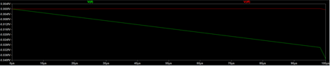
so I'm trying to design a frequency-mixer circuit. (the images are all shown below) in LTSpice, and there's a task asking me to perform a transient analysis at 100 microseconds, and find the time it takes the voltage at IFF to reach steady-state value. however, when i plotted the graph, the line (the red line in the picture) seems to be a straight line from start to finish, instead of reaching a point where the values will cease to change. is there something wrong with my schematic? or did i understand something wrong?

all the pictures in order:

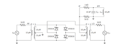
1. the original schematic
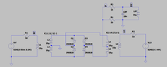
2. my schematic

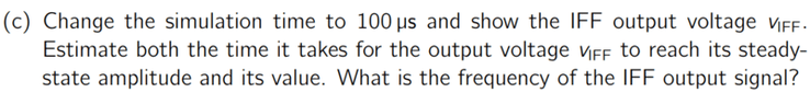
3. the task in question

4. my graph ( V IFF is the red line)
 

Attachments

  • Capture.PNG
    Capture.PNG
    9.5 KB · Views: 372
  • schematic a.PNG
    schematic a.PNG
    12 KB · Views: 310
  • question.PNG
    question.PNG
    13.4 KB · Views: 293
  • schematic c.PNG
    schematic c.PNG
    3.4 KB · Views: 297
Physics news on Phys.org
Welcome to PF.
An LTspice schematic.asc file is an ASCII text file. There can be things in your schematic.asc file that are invisible on the screen image.
If you copy and rename the file as schematic.asc.txt you can then attach it to your post and I can run it here.
 
  • Like
Likes DaveE and berkeman
LTspice requires 4 MHz to be written as 4MEG, 4meg or 4e6.
Where you use a capital M, I expect you are getting millihertz, not Megahertz.
3.5M = 3.5 millihertz. Try 3.5MEG or 3meg5
 
Last edited:
  • Informative
  • Like
Likes minhha04 and berkeman
Baluncore said:
LTspice requires 4 MHz to be written as 4MEG, 4meg or 4e6.
Where you use a capital M, I expect you are getting millihertz, not Megahertz.
3.5M = 3.5 millihertz. Try 3.5MEG or 3meg5
you are right! I changed it to MEG and it worked, thank you so much!
 
  • Like
Likes berkeman
minhha04 said:
I changed it to MEG and it worked, thank you so much!
That is all part of the service we offer. You did the right thing asking here. The SPICE learning curve is steep, and there are some overhangs. There are also some shortcuts you will find out about later. The M or MEG gets everyone sometime.

Avoid including units in component values. The trap I like best is the one farad capacitor, 1F, that seems not to be connected.
The F is interpreted not as a farad, but as femto = 1e-15.

Search LTspice Help for MEG to find the SI prefixes. They were hidden at the end of the “General Structure and Conventions” page.
 
  • Informative
Likes berkeman
Be aware that a frequency mixer is a Large Signal "device".

Small Signal analysis in SPICE (.AC) will NOT give you the right answer. Specifically diode mixers (or any other type) will not "mix" without large signal, NONLINEAR excursions of the diodes. This is central to how any mixer works - it has to "switch" in order to achieve the nonlinearity required. So this implied you must use .TRAN or large signal transient simulation.

The mixing action comes from higher order polynomial terms of the mixing device that give you minimially square law (2nd order) or higher terms which then give you "cos RF cos LO = ..." trig identity terms which results in terms that look like cos (RF+LO) + cos (RF-LO).
 
Baluncore said:
LTspice requires 4 MHz to be written as 4MEG, 4meg or 4e6.
Where you use a capital M, I expect you are getting millihertz, not Megahertz.
3.5M = 3.5 millihertz. Try 3.5MEG or 3meg5
That is sooo annoying. I know it and still regularly screw it up.
 

Similar threads

  • · Replies 17 ·
Replies
17
Views
3K
  • · Replies 12 ·
Replies
12
Views
2K
Replies
7
Views
2K
Replies
9
Views
7K
  • · Replies 4 ·
Replies
4
Views
4K
  • · Replies 3 ·
Replies
3
Views
2K
  • · Replies 15 ·
Replies
15
Views
6K
Replies
24
Views
7K
  • · Replies 4 ·
Replies
4
Views
5K
  • · Replies 14 ·
Replies
14
Views
3K