BJT differential amplifier, small signal analysis

Join the discussion
Registration is free. Start your own thread to ask a follow-up.
11 replies · 8K views · last reply
eliotsbowe
Messages
34
Reaction score
0
Hello, I'm having some issues with small-signal analysis of BJT differential amplifiers.

Let's say I have this BJT differential pair and suppose that Q1 and Q2 perfectly match: http://i50.tinypic.com/14ahdgn.jpg

Suppose a small differential input is applied and consider the small–signal equivalent circuit:
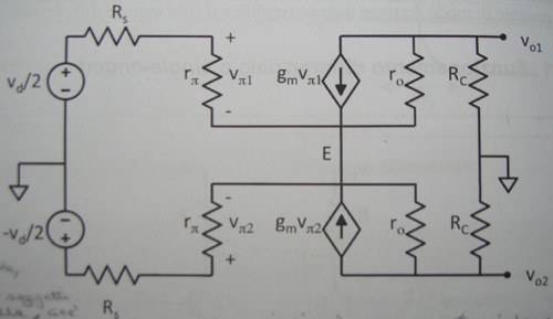
Small-signal equivalent circuit of a BJT differential pair with inputs +vd/2 and -vd/2 through Rs, each base resistance rπ, transconductance gm vπ, output resistance ro and collector resistance Rc, with the emitter node E labeled and outputs vo1 and vo2.


Having two opposite-phase inputs with the same amplitude ([itex]\frac{v_d}{2} , - \frac{v_d}{2}[/itex]) makes the potential of the emitter E stuck at its initial value.

My book says that:
- If the potential of E is stuck at its value, then E can be considered as a ground point for the small-signal circuit;
- If E is grounded, then every point the two circuits have in common is grounded; this means that the two circuits become totally independent one from each other and I can solve the small-signal circuit of Q1 and Q2 separately;

Can anyone please explain me the reason for these two statements?

One last question: both small-signal circuits of Q1 and Q2 have an input impedance [itex]r_\pi[/itex] and an output impedance Rc || [itex]r_o[/itex].
What's the input/output impedance of the whole differential pair?

Thanks in advance for your time.
 
Engineering news on Phys.org
Thanks. I managed to solve the first two questions and I found something I was looking for in the pdf you've linked.

Now there's one pending question: what's the input/output impedance of the differential couple?

I mean: if I connect some circuit component to the two inputs of the differential amplifier, what impedance is the component going to "see"?
 
Don't quote me on this as it's been a long time. I believe is [itex]2βr_e=2\frac β {g_m}\;[/itex]. The emitter of one transistor only see the [itex]r_e\;[/itex] of the other, assuming the tail resistor is much higher resistance.
 
Well, thanks for trying, but I'm interested in the procedure to find the two impedances!
 
I am pretty sure it is correct, input impedance of diff pair is not low. It become high impedance only when you add negative feedback and move the other side to follow the input.

Think about a normal diff pair in an opamp, the tail current say is 10uA. So it is 5uA each.

[tex]r_e=1/gm= \frac {V_T}{I_c}≈\frac {25mV}{5\mu A}=5000,\;\; β=100\;\Rightarrow 2β r_e= 1MΩ[/tex]

That is in the ball part of the input impedance of some opamp when it is open loop. The impedance only get higher due to negative feedback.
 
Last edited:
eliotsbowe,

Now there's one pending question: what's the input/output impedance of the differential couple?

I mean: if I connect some circuit component to the two inputs of the differential amplifier, what impedance is the component going to "see"?

You can tell just from inspection of the schemat what the impedances will be. Assuming ro is very high, the input circuit goes through the two r_pi resistors, so the impedance will be 2*r_pi. The output impedance is 2*Rc by inspection if ro is very large. Otherwise I would think it would be 2*Rc||ro/(β+1), because the output impedance of a single CE transistor diminishes by ro/(β+1)

Ratch
 
I disagree with output impedance of a single CE amplifier is not equal ro/(β+1).
As for differential output impedance Rout = (2Rc*ro)/(Rc + ro)
 
Okay, I think I got it.
Just one thing: to compute the input impedance of a circuit, I usually disconnect the signal generator and its own resistance and replace it with a test generator, let's say a voltage generator Vx. The input impedance is defined as Vx / Ix , where Ix is the current flowing through the generator.

If I want to apply this method to the differential pair, I guess I should disconnect both [itex]\frac{v_d}{2}[/itex] and [itex]-\frac{v_d}{2}[/itex] (and the two [itex]R_s[/itex] resistors) and replace them with a test generator connected between the positive terminals of the two [itex]r_\pi[/itex] resistors.
Is this right?
 
Yes, you use this circuit to find Rin
Small-signal equivalent circuit of a BJT differential pair with two r_pi, g_m v_pi and r_o branches, collector resistors R_C, outputs v_o1 and v_o2, a shared node E, and a test source Vt with series R_s and current It.


And this one to find Rout
Small-signal half-circuit diagram of a BJT differential amplifier with Rs, r_pi, gm v_pi, r_o and R_C in each half, a test voltage source Vt, and outputs vo1 and vo2 joined at node E.

And from this diagram when we assume full symmetry. From the inspection we can see that
Rout = Vt/It = 2Rc||2ro
 
Attachments
  • Small-signal hybrid-pi equivalent circuit of a BJT differential amplifier, with source resistors Rs, voltage source Vt and current It, resistances rπ, transconductance sources gm vπ1 and gm vπ2, output resistances ro, collector resistors Rc, and outputs vo1 and vo2 with node E.
    2ea.JPG
    13.5 KB · Views: 1,096
  • Small-signal half-circuit for a BJT differential amplifier with two transistor branches, each with rπ, gm vπ, ro and RC, joined at node E, with source resistors Rs, a test voltage source Vt and outputs vo1 and vo2.
    2eaj.JPG
    14.7 KB · Views: 1,084
Last edited:
Jony130,

Sorry I did not get back sooner.

I disagree with output impedance of a single CE amplifier is not equal ro/(β+1).
As for differential output impedance Rout = (2Rc*ro)/(Rc + ro)

Yes, you are correct. The output impedance of a CE is ro/(β+1) only if it is driven by a current source. Otherwise, in this voltage driven case, it is ro as you pointed out.

Ratch