rdemyan
- 67
- 4
- Homework Statement
- Convert a lab frame diagram to center of mass reference frame
- Relevant Equations
- See post
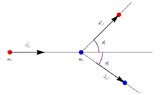
I'm trying to convert the first attached diagram to the center of mass (zero momentum) reference frame. Two particles (##m_1, m_2##) collide at an angle at respective velocities of ##u_1, u_2##. The drawing inherently assumes that the momentum of the 2nd particle is greater than that of the first particle (but of course it could be the reverse or they could even have equal momentums). After the collision, the two particles scatter at angles of ##\alpha## and ##\phi##. Because the momentum of particle 1 is greater, I believe it will go to the right and particle 2 to the left. Let's assume that is the case.
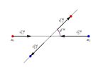
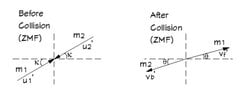
The second diagram converts to the COM or ZMF reference frame. I show what I think the before and after the collision might look like in the COM reference frame. But I'm not sure that these are correct.
My question regards the angles in the COM reference frame. Is the angle of the center of mass only applicable to the drawing that shows after the collision (ZMF)? If so, is it measured from the x axis (as ##\theta## is shown to be) or is it possible that it is measured relative the angle ##\kappa## shown in the before collision (ZMF) drawing? I'm just not sure how the COM angle is defined in this case. Virtually every document or video on this topic (available on the web) is for a situation where ##\kappa## is equal to zero. Also in the lower left quadrant should the angles be shown as ##-\kappa## and ##-\theta## for each drawing respectively?
Attachments

Last edited: