Creating a Contour System: Results

In summary, the conversation discussed the issue of voltage drops in a circuit with two closed circuits and a current source. The poster was having trouble understanding the relationship between the current and voltage drops and was seeking clarification on the correct solution. Upon further discussion and clarification, it was determined that the initial solution provided in the photo was correct. The thread has been closed for moderation. The poster was reminded to post in English and to use the Reply/Quote function carefully.
  • #1
abvg
4
0
Homework Statement
I probably have the right solution, but I don't understand it. the problem with my solution, it seems to me, is that on each selected circuit, the sum of voltage drops includes an extra voltage drop
Relevant Equations
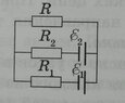
find the current through the resistor R in the circuit (attached to the question) if E1 = 1.5V , E2= 3.7V, R1 = 10 ohms , R2= 20 ohms , R = 5 ohms. the internal resistance of the current source is not taken into account
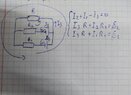
выбранный контур контура и получившаяся система также показана на фото.
 

Attachments

  • IMG_20230316_080328.jpg
    IMG_20230316_080328.jpg
    37 KB · Views: 51
  • IMG_20230316_081828.jpg
    IMG_20230316_081828.jpg
    48.3 KB · Views: 49
Physics news on Phys.org
  • #2
abvg said:
on each selected circuit, the sum of voltage drops includes an extra voltage drop
I'm not understanding your difficulty. Can you expand on that?
 
  • Like
Likes MatinSAR
  • #3
Rules Violation - Member warned that per forum rules, posts must be in English.
haruspex said:
Я не понимаю ваших затруднений. Можете ли вы расширить это?

haruspex said:
Я взял 2 замкнутых контура. рассмотрим небольшой, где есть источник тока с Е2, в этой цепи через резистор R проходит ток I3, а падение напряжения там RI3. мне непонятно, что источник тока Е2 создает ток I2 и он "соединяется" с I1 проходит через R почему мы думаем что падение напряжения на R+I2R2 полностью равно Е2, ведь вклад Е2 в падение напряжения на R должно быть I2R. Я также представил, что было бы, если бы не было источника тока с Е1, в данном случае Е2 = RI2+R2I2. это, как мне кажется, опровергает якобы "правильное" решение. мне бы очень помогло, если бы у меня было действительно правильное решение и объяснение для него.
 
  • #4
abvg said:
I took 2 closed circuits. Let's consider a small one where there is a current source with E2, in this circuit the current I3 passes through the resistor R, and the voltage drop there RI3. I do not understand that the E2 current source creates a current I2 and it "connects" to I1 passes through R why do we think that the voltage I also imagined what would have happened if there had not been a current source with E1, in this case E2 = RI2+R2I2. it seems to me that refutes the allegedly "right" solution. It would help me a lot if I had the right decision and explanation for it.

Well, you can take it in smaller steps. Assign a voltage variable to the left hand side and write the V=IR equation for each resistor.
I do not see how the no E1 case shows your method to be wrong.
 
  • Like
Likes MatinSAR
  • #5
haruspex said:
Я не понимаю, как случай без E1 показывает, что ваш метод неверен.
если выключить участок цепи с Е1, то останется только цепь, где есть Е2, R, R2 и ток в этой цепи будет силой I2, что следует из второго правила Кирхгофа, что Е2 = I2(R + Р2). Мне интересно ваше мнение, как вы считаете решение, изложенное на фото, правильно?
haruspex said:
Ну, вы можете сделать это небольшими шагами. Назначьте переменную напряжения в левой части и запишите уравнение V = IR для каждого резистора.
IMG_20230316_102032.jpg вот так? А что дальше?
 
  • #6
abvg said:
если выключить участок цепи с Е1, то останется только цепь, где есть Е2, R, R2 и ток в этой цепи будет силой I2, что следует из второго правила Кирхгофа, что Е2 = I2(R + Р2). Мне интересно ваше мнение, как вы считаете решение, изложенное на фото, правильно?

View attachment 323669 вот так? А что дальше?
IMG_20230316_102650.jpg думаю это верно
 
  • #7
abvg said:
If you turn off the section of the circuit with E1, there will only be a chain where there is E2, R, R2 and the current in this circuit will be force I2, which follows from Kirchhoff's second rule that E2 = I2(R + P2).
Yes, but that does not tell me why you think that contradicts your equations in post #1.
Note that you cannot just set ##E_1## to zero. You have to set ##I_1=0, R_1=\infty##.
I believe your post #1 solution is correct.
 
  • #8
Thread closed for Moderation...
 
  • #9
After a Mentor discussion, this version of the thread will remain closed.

@abvg -- Please always take care to post in English on PF, and not rely on others to do the translations to try to understand you and help you. Also, please take care with the Reply/Quote function -- in a number of the posts above you've represented your reply as a quote from @haruspex which is very confusing.
 

1. What is a contour system?

A contour system is a method used to represent the 3-dimensional shape of an object or surface on a 2-dimensional plane. It involves drawing lines or curves that connect points of equal elevation or value on the object or surface.

2. Why is a contour system important?

A contour system is important because it allows us to visualize and analyze the shape, elevation, and characteristics of an object or surface. It is commonly used in fields such as geography, geology, and engineering to create maps and models.

3. How do you create a contour system?

To create a contour system, you first need to gather data about the object or surface you want to represent. This can be done through measurements, surveys, or other methods. Then, you can use the data to plot points of equal value and connect them with lines or curves to create the contour lines.

4. What are the benefits of using a contour system?

Using a contour system can provide a more accurate and detailed representation of an object or surface compared to other methods. It also allows for easier interpretation and analysis of the data, as well as the ability to identify patterns and trends.

5. What are some common challenges when creating a contour system?

Some common challenges when creating a contour system include obtaining accurate and precise data, determining the appropriate interval for contour lines, and dealing with irregular or complex shapes. It is also important to consider the scale and projection of the contour system to ensure accurate representation.

Similar threads

  • Engineering and Comp Sci Homework Help
Replies
8
Views
352
  • Introductory Physics Homework Help
Replies
4
Views
3K
  • Introductory Physics Homework Help
Replies
15
Views
1K
  • Introductory Physics Homework Help
Replies
2
Views
1K
  • Introductory Physics Homework Help
Replies
6
Views
2K
Replies
12
Views
2K
  • Programming and Computer Science
Replies
1
Views
1K
  • Mechanics
Replies
13
Views
982
Replies
5
Views
1K
  • Introductory Physics Homework Help
Replies
1
Views
2K
Back
Top