Designing a Geneva Mechanism: Overcoming Challenges

AI Thread Summary
The discussion revolves around designing a Geneva mechanism with a focus on achieving intermittent motion while overcoming issues like jamming and dragging. The designer is experimenting with various configurations, including the use of a locking mechanism and different pin arrangements. Challenges include ensuring proper engagement and disengagement of pins while minimizing the number of components. Suggestions include modifying traditional designs and considering alternative mechanisms like cams and gears to facilitate the push-pull motion required. The conversation highlights the importance of asking the right questions to stimulate innovative solutions in mechanical design.
DefinitelyAnEnjinear
Messages
10
Reaction score
6
TL;DR Summary
Discussing the practical and moral limitation of mounting the driving pin on the driven wheel in a geneva mechanism.
(note: I never studied engineering, but I think I have a good math (and slight physics) background. I'm mentioning this not so you'll go easy on me - if I don't understand something, I'm sure I'll figure it out or find someone to help me decode what you're saying. I'm mentioning this in the hopes you'll forgive mistakes or failures to communicate that may seem obvious to you.)

A while ago, I posted about a geneva mechanism I was trying to design.

My goal was to have the driving pin mounted on the driven wheel, pushing against something that doesn't move (either a dial pushing against some pins as in my latest attempt, or a gear with a single tooth pushing against a gear) to cause the intermittent motion.

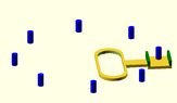
An earlier attempt I posted:


as someone pointed out, this one lacked a locking mechanism.
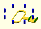
I've designed one with a locking mechanism, which overcame a previous problem (dragging) but not my jamming problem - when the dial engages the pins/the tooth egnages the gear and the driven wheel is supposed to rotate, it gets stuck.

As can be seen in the gif I posted, if I cheat and rotate the gear mounted on the driven wheel myself (rather than driving it through a gear in the center), it works - not just in the version without a lock, but in the one with a lock as well.

I don't have a video of a version with a locking mechanism to share (I've allowed myself to lose track of the 3D printed pieces of some of the attempts because I planned on making more attempts before asking for help again, but my attempts to get my 3D printer to print properly have all failed so far)

my latest design (the one that I hadn't managed to print - a previous one with a gear instead of pins and a 1-toothed gear instead of a dial that I did print also didn't work)

Untitled2.png
 
Engineering news on Phys.org
The traditional Geneva mechanism has a continuously rotating input wheel, with a single driving-pin, and a disc-segment lock. The output disc moves intermittently, it has several driven slots, with arcs in between, that engage the input lock while it is not advancing.

As I understand it, you want to have a single slot on the input disc, and several pins on the output disc. Why?

What is the reason for the inverted design?

I notice the missing segment of the lock disc in your yellow model is too narrow to allow the driven disc to move. Have you considered using the missing segment of the drive lock as the slot that drives the output disc? Maybe replacing the multiple cylindrical pins with a non-circular projection.
 
  • Like
Likes DefinitelyAnEnjinear
Baluncore said:
As I understand it, you want to have a single slot on the input disc, and several pins on the output disc. Why?
I don't follow what you're calling input and output, since in the traditional design the driving pin (here, a dial-in green) is the input.
The pins are on a part that will remain stationary, for the dial (in green) to push against. As for a slot on the input disc, do you mean the top, smaller gear? the slot there is just so I can connect it to the rest of the pieces (these designs were done with 3D printing in mind).

Baluncore said:
Have you considered using the missing segment of the drive lock as the slot that drives the output disc?
If you're talking about something like this
1658408703633.png

I have tried to understand the math behind its design before, perhaps I should give it another go. I went with something I knew how to design and didn't really consider this design when I ran into the jamming problem (since I wasn't even sure if what I'm trying to do is feasible, thanks to my lack of engineering knowledge...)
Baluncore said:
What is the reason for the inverted design?
That's a bit complicated:
I have 8 pins uniformly distributed on a circle. I need to push, then pull each one of them sequentially, and I'm trying to use as few parts as possible (so having one mechanism for each pin is not an option).
I can't have a mechanism that is always engaged with the pins either - it needs to engage, push, pull, disengage.
To do the pull+push, I figured I would go with a scotch yoke.
here's a quick mockup:
ezgif.com-gif-maker(3).gif

I can't have the pin driving the scotch yoke rotate around the center axis, because I need to mount more things above it on the same axis. so since the pin driving the scotch yoke can't rotate around the central axis, I came up with the idea of having a geneva mechanism with the driving pin/dial (the green part in my geneva mechanism design) mounted on the geneva wheel, and I will have the pin driving the scotch yoke mounted on the same axis as the driving pin for the geneva mechanism.... I hope that all made sense
I'm going to try and understand how to design the normal geneva mechanism I posted and see if that one doesn't jam up on me.
 

Attachments

  • 1658409672970.png
    1658409672970.png
    5.3 KB · Views: 195
  • 1658412519182.png
    1658412519182.png
    3.7 KB · Views: 171
DefinitelyAnEnjinear said:
I don't follow what you're calling input and output, since in the traditional design the driving pin (here, a dial-in green) is the input.
One pin with several slots is traditional. Keeping the same base, inputs and outputs, swap pins and slots. Just which component you fix is up to you, but try to keep the discussion traditional.

DefinitelyAnEnjinear said:
I have 8 pins uniformly distributed on a circle. I need to push, then pull each one of them sequentially, and I'm trying to use as few parts as possible (so having one mechanism for each pin is not an option).
I can't have a mechanism that is always engaged with the pins either - it needs to engage, push, pull, disengage.
I would arrange a single rotating actuator disc with a cam that pushes the pin away, with a small rocker or guide operated by the same cam to push the pin back.

The critical thing about the design is the connections to the circle of pins. How do they extend up and down? Without that detail, it is not possible to see solutions that are simpler than the Geneva mechanism.

This is a bit like the design of a circular knitting machine, used to make socks.
https://en.wikipedia.org/wiki/Knitting_machine#Types
Google 'circular knitting machine' to see plastic examples for sale.
 
  • Like
Likes DefinitelyAnEnjinear
tl;dr since you made me think about a normal geneva mechanism again, I'm almost certain I found a pretty simple way to modify it to meet my needs. Guess I just needed someone to force me to explain things and a reminder of what a normal geneva mechanism looks like.
I left everything I wrote as it is, and my solution is at the end.
I appreciate the help!
(and the circular knitting machine was interesting. watched a video)


Baluncore said:
The critical thing about the design is the connections to the circle of pins. How do they extend up and down? Without that detail, it is not possible to see solutions that are simpler than the Geneva mechanism.
The pins on the circle would be at the ends of sticks. The sticks will rest on 2 different holes(?), constrained to only move in the desired direction (we can ignore the possibility of the sticks deforming)
1658475892305.png

For my purposes, it doesn't matter whether the pin faces up or down

Baluncore said:
I would arrange a single rotating actuator disc with a cam that pushes the pin away, with a small rocker or guide operated by the same cam to push the pin back.
I considered a mechanism that was purely a cam in the past
1658474900811.png

Imagine this rotating around the blue circle. The curved lines within the square would be raised, and it would push and then pull the pin back as it rotated.

This would've been ideal - incredibly simple, with one piece. But I tried it, and it applied too much force to the side and not enough up/down.

To make it work I would have to make everything too big so the lines would have an angle that would impart more force in the forward/backward direction.

(I also had no idea how to design the ideal curve as a function of the angle over which I want it pushed forward and then backward. The forward+backward motion has to be completed over 45 degrees, and I'm guessing the force applied forward and to the side depend on the cosine and sine of the angle at the point of contact...)

A rocker would be fine with me, but it can't be mounted on the center axis (which is the only point that's equal distance from all the pins) because I need to put more things above it on the central axis.

And since it can't be mounted on the central axis, I see no alternative other than having it orbit around the central axis, which brings me back here.


... although I am getting a new idea now
1658476753970.png

I could have a gear as part of the green part (pin+lock) to drive a gear mounted on the same axis as the output, which, in turn, will drive the mechanism I would use to do the push+pull
1658477135902.png

here star = gear, and the blue gear would be mounted on the output wheel (red part) and operate whatever mechanism pushes and pulls.

... I'm a bit disappointed with myself for not thinking about this earlier. It was so simple
 
DefinitelyAnEnjinear said:
... I'm a bit disappointed with myself for not thinking about this earlier. It was so simple
You need a good question to release a good solution. My answer is often a question, intended to provoke a reader into thinking or looking at things differently. The answer was within you all the time.

One engineer told me that he tried to phone me to talk over a weird problem, but I did not answer, so he asked himself; “What questions would Baluncore ask in this situation?”. He promptly solved the problem without me, so I missed out on an interesting story.

Experienced engineers and scientists learn to ask themselves provocative questions. When you get stuck, ask; "What answers would I get if I posted this question on PF?". That will give you access to the limits of your imagination. If that is insufficient, don't feel bad, just post the question on PF, which will also stimulate others to keep thinking.
 
  • Like
Likes hutchphd, DefinitelyAnEnjinear and Lnewqban
How did you find PF?: Via Google search Hi, I have a vessel I 3D printed to investigate single bubble rise. The vessel has a 4 mm gap separated by acrylic panels. This is essentially my viewing chamber where I can record the bubble motion. The vessel is open to atmosphere. The bubble generation mechanism is composed of a syringe pump and glass capillary tube (Internal Diameter of 0.45 mm). I connect a 1/4” air line hose from the syringe to the capillary The bubble is formed at the tip...
Thread 'Physics of Stretch: What pressure does a band apply on a cylinder?'
Scenario 1 (figure 1) A continuous loop of elastic material is stretched around two metal bars. The top bar is attached to a load cell that reads force. The lower bar can be moved downwards to stretch the elastic material. The lower bar is moved downwards until the two bars are 1190mm apart, stretching the elastic material. The bars are 5mm thick, so the total internal loop length is 1200mm (1190mm + 5mm + 5mm). At this level of stretch, the load cell reads 45N tensile force. Key numbers...
I'd like to create a thread with links to 3-D Printer resources, including printers and software package suggestions. My motivations are selfish, as I have a 3-D printed project that I'm working on, and I'd like to buy a simple printer and use low cost software to make the first prototype. There are some previous threads about 3-D printing like this: https://www.physicsforums.com/threads/are-3d-printers-easy-to-use-yet.917489/ but none that address the overall topic (unless I've missed...
Back
Top