Hitman6267
- 17
- 0
Electric Circuit. Norton/Thevelin Equivalents
Unsolved Problem
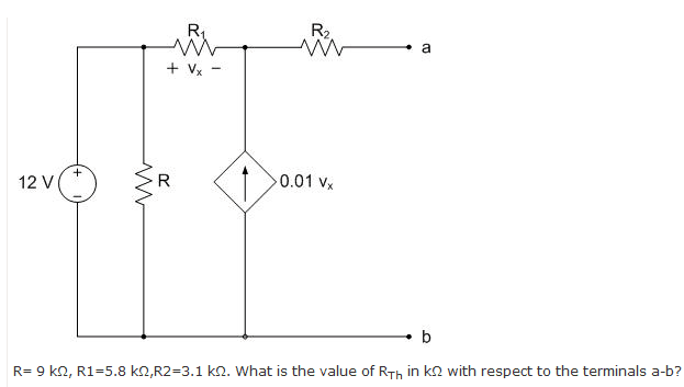
I used a node voltage equation to try and get Vth and the I in the short-circuit to get the Rth but it didn't work.
Unsolved Problem
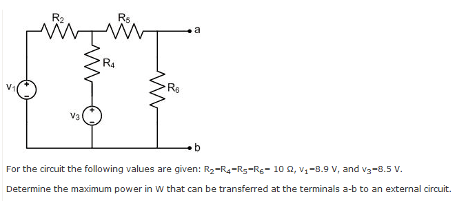
I used a node voltage equation to get Vth and I in the short-circuit. Got Rth and used in the in Vth^2 / 4 RL (with RL = Rth)
My answer was wrong. Is the method correct ?
Solved this my self
Removed to make space for another problem
For me, I find that the Norton equivalent is going to be 12A since the independent current source forces that ampage. But apparently I'm wrong. (I get feedback from a web form when I submit the answer). Any one can tell me what's wrong with my thought process ? Thank you.
Solution:
After doing a source transformation and adding up the resistors. You can get the correct the Norton current value.
Solved
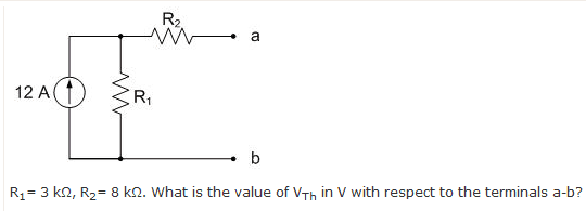
I thought that if I did a source transformation getting a 36000V source would solve the problem because there isn't any other voltage source in the circuit. I was wrong. Any hints on this one ?
Unsolved Problem
I used a node voltage equation to try and get Vth and the I in the short-circuit to get the Rth but it didn't work.
Unsolved Problem
I used a node voltage equation to get Vth and I in the short-circuit. Got Rth and used in the in Vth^2 / 4 RL (with RL = Rth)
My answer was wrong. Is the method correct ?
Solved this my self
Removed to make space for another problem
For me, I find that the Norton equivalent is going to be 12A since the independent current source forces that ampage. But apparently I'm wrong. (I get feedback from a web form when I submit the answer). Any one can tell me what's wrong with my thought process ? Thank you.
Solution:
After doing a source transformation and adding up the resistors. You can get the correct the Norton current value.
Solved
I thought that if I did a source transformation getting a 36000V source would solve the problem because there isn't any other voltage source in the circuit. I was wrong. Any hints on this one ?
Last edited:
