anvoice
- 16
- 3
- TL;DR
- A sanity check on a text I am using to learn EE. Cannot replicate the result for the common mode Thevenin resistance in a figure in the text.
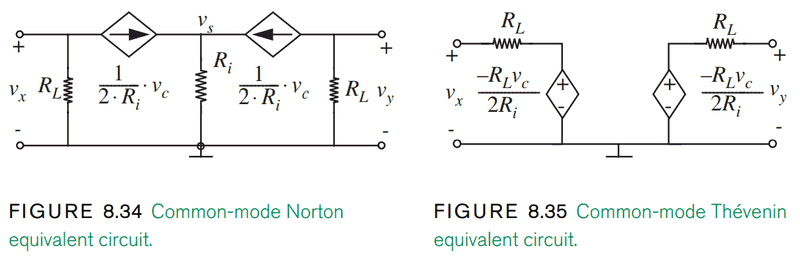
I am currently reading about small signal analysis of a MOSFET differential amplifier. The text I am using has the below two figures for a common-mode equivalent circuit for the amplifier. The first makes sense to me except where it calls it a "Norton equivalent circuit", whereas I thought a Norton between either the vx or vy terminals would need to have a single resistance in parallel with a current source, and I don't see how this qualifies.
More importantly, the second figure has the Thevenin equivalent resistance as just RL. Seeing that exciting the subcircuits on the leftmost figure with a voltage and measuring the current seems to be a reasonable way of finding Rth in this case, I did that and ended up with a Rth of
2RL / (2 + (RL) x (vc)). Am I missing something major or is this a typo in the text? Granted it doesn't invalidate the main result (vx - vy = 0), it bothers me.
More importantly, the second figure has the Thevenin equivalent resistance as just RL. Seeing that exciting the subcircuits on the leftmost figure with a voltage and measuring the current seems to be a reasonable way of finding Rth in this case, I did that and ended up with a Rth of
2RL / (2 + (RL) x (vc)). Am I missing something major or is this a typo in the text? Granted it doesn't invalidate the main result (vx - vy = 0), it bothers me.