Electric field lines next to conductor

mzh
Messages
61
Reaction score
0
Dear Physics Forums readers
Let a two dimensional rectangle R1 carry a surface charge [itex]\sigma[/itex] and be placed next to another rectangle R2 of the same shape made from metal (i.e. a conductor). What does the electric field look like close to the second rectangle?

My intuition would tell me, the field lines terminate on the close side of R2, causing accumulation of negative charge on the side close to R1 and positive charge on the far side which in turn emits a field. The net field could be seen as reaching through R2.

I tried to verify this using a finite element simulator and obtained the following image for the field (R1 left, R2 right):
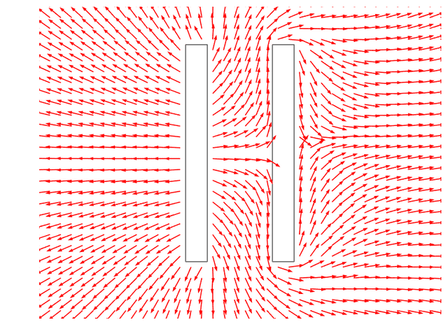
field-metal.png


Now it seems to me as if the field goes around the metal. Is that correct? Or can the field only terminate *on* opposite charges?
 
on Phys.org
Or can the field only terminate *on* opposite charges?
It has to - a surface charge corresponds to electric field lines perpendicular to the surface.
In addition, the parallel component of the field has to vanish at the surface (the potential is constant).
 
It seems to me that the simulation is incorrect. The positive charge of the object on the left should induce a separation of charge in the object (conductor) on the right, so that its left surface acquires a negative charge and its right surface acquires a positive charge. The net charge of the conductor would of course remain zero. The electric field close to those surfaces would not be parallel to those surfaces.
 
It doesn't look right to me (But I've always had a blind spot when it comes to field lines)

The electric charges inside the conductor rearrange themselves slightly in such a way as to neutralise the field at the surface. The field is prevented from entering the conductor.

I would have expected the lines to terminate on the surface charge and start again from the other side as you did.

There's no intensity variation shown in the diagram, only directions - that may be the problem.
 
mzh - what kind of simulation software was it? Field patterns look awfully like fluid flow to me - with LHS rectangle acting as a source, and RHS rectangle simply as an obstacle. Fluid flow then has to be pretty slow to avoid vortices around RHS rectangle. And btw it would have been better to have labelled the rectangles in pic, specified sign of charge, and that charge distribution was either fixed or formed an equipotential on the source rect. But a nice idea to provide a pic that can be viewed without needing to log in first.
 
Thanks guys for the feedback.
@mfb: Ok. And can it also terminate on induced charges?
@{jtbell,AJ Bentley}: that's exactly what i was expecting. In the simulator, R2 is assigned a "metal" property. But I don't know if it can plot the actual charge distribution. Yeah, did not show the intensity of the field, but its of secondary importance to me currently.
@Q-reeus: I used COMSOL (AC/DC module). I don't think its going into PRL, so i left out the labels ;) Sign of charge should be clear from field direction on R1, no?
 
mzh said:
@Q-reeus: I used COMSOL (AC/DC module). I don't think its going into PRL, so i left out the labels ;) Sign of charge should be clear from field direction on R1, no?
Fair enough for last point, but it's always best to give a 'verbal' to such things anyway. So given this COMSOL is an AC/DC simulation, my guess is you have plotted a current flow - giving direction but not intensity, and with R2 an insulator. But that puzzles me because you say R2 was given a metal property.
 
Without intensity, E-field direction is pretty meaningless. That's why you get an apparently large 'flow' of field around the conductor. In reality that field is virtually non-existent. It's just a residual component.
 
mzh said:
@mfb: Ok. And can it also terminate on induced charges?
Right. Induced or not, a surface charge density implies a non-zero field strength (outside), which corresponds to ending field lines.
 
  • #10
AJ Bentley said:
Without intensity, E-field direction is pretty meaningless. That's why you get an apparently large 'flow' of field around the conductor. In reality that field is virtually non-existent. It's just a residual component.

Sure. I'll see what I get when considering the intensity.

To return to my main point of the thread (i'm not so much interested in how correct my simulation is done or not).

Given the above system (surface charge on R1, metallic R2). What will the field look like, say from textbook undergraduate physics?
 
  • #11
Between the plates: Nearly homogeneous (from left to right in the sketch)
To the right of the right plate: nearly homogeneous (away from the conductor)
Far away: Similar to a single charged object.
In between: Let the computer calculate it
 
  • #12
@mfb: thanks. i would think the same. something must be fishy with my simulation then.
 

Similar threads

  • · Replies 7 ·
Replies
7
Views
2K
  • · Replies 22 ·
Replies
22
Views
3K
  • · Replies 4 ·
Replies
4
Views
3K
  • · Replies 1 ·
Replies
1
Views
2K
  • · Replies 14 ·
Replies
14
Views
3K
  • · Replies 8 ·
Replies
8
Views
2K
  • · Replies 3 ·
Replies
3
Views
3K
  • · Replies 73 ·
3
Replies
73
Views
7K
  • · Replies 2 ·
Replies
2
Views
2K
  • · Replies 25 ·
Replies
25
Views
3K