Electrical Engineering - circuits - Reactive Networks

Join the discussion
Ask a follow-up here, or get your own question answered by working scientists, mathematicians and engineers — people, not an autocomplete.
Real named experts · corrections over time · the nuance an AI answer skips
62 replies · 8K views
Frankboyle
Messages
25
Reaction score
0
1. Homework Statement
There are multiple parts to this question, but I have only got through the first 2 before getting stuck. Please could somebody give me a hand as I am really struggling :frown:

(a) Calculate the phasor voltage of the voltage source and the phasor current of the current source in both Cartesian and Polar coordinates. Use peak values when calculating the phasors.

(b) What are the phasor voltage and impedance of the Thevenin equivalent circuit of the power supply? (Use peak values for the voltages and currents in your calculation)

(c) What are the phasor current and impedance of the Norton equivalent circuit of the power supply? (Use peak values for the voltages and currents in your calculation)

(d) At what frequency should the circuit operate for the current flowing through the load and the voltage across it to be in phase?

(e) It is known that for a different load the voltage and current across the load are 240cos(ωot+45°) V and 4cos(ωot+60°) A, respectively. How much power is dissipated in that load?
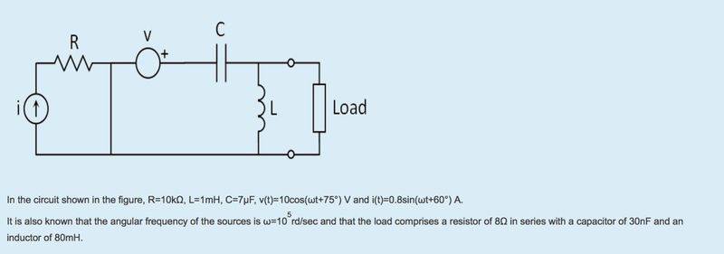
Screen_Shot_2016_01_29_at_14_52_10.png

Homework Equations

The Attempt at a Solution


These are my attempts at part a, but I was unsure whether they're correct or not
(a)
Voltage source:

|V| = 10 V; Φ = 75°

V = 2.5882 + j 9.6593 V

Current source:

|I|=0.8 A; Φ = -30°

I=-0.4 + j 0.6928 A

 
Last edited by a moderator:
on Phys.org
Your voltage source phasor looks okay, but your Cartesian form for the current source does not. You have correctly transformed the sine function to a cosine, but the components that you calculated aren't right. It's a good idea to make a quick sketch of the phasor to confirm that your components look reasonable.
 
  • Like
Likes   Reactions: gracy
I've re-calculated i(t) and for the cartesian my answer is 0.6929 -j0.4.

As for the short circuit, yes I believe that is one
 
Part (b) requires the circuit to be reduced using Thevenin's theorem, so the overall circuit contains just a single voltage source and a series impedance. I'm not entirely sure how to go about it however
 
What's the "algorithm" for determining a Thevenin equivalent?
 
  • Like
Likes   Reactions: gracy
What do you mean exactly?
 
What is the procedure to apply to determine a Thevenin equivalent?
 
  • Like
Likes   Reactions: gracy
Firstly, remove the load and create an open-circuit. This renders both the current and voltage sources as 0.

Secondly, I would draw up the remaining circuit which would only contain the remaining resistor, capacitor and inductor.

Thirdly, I would work out the impedance for each of these components. I would then combine them into one impedance for the entire circuit.

From there I am unsure what to do
 
I think you should review your course notes or text for a description of the procedure and worked examples.
Frankboyle said:
Firstly, remove the load and create an open-circuit. This renders both the current and voltage sources as 0.
No, that will only remove the load. The sources will still be active. You have to "manually" suppress the sources if want them suppressed. But removing the load is a correct first step.
Secondly, I would draw up the remaining circuit which would only contain the remaining resistor, capacitor and inductor.

Thirdly, I would work out the impedance for each of these components. I would then combine them into one impedance for the entire circuit.
Yes, that will yield the Thevenin impedance. But you still need to find the Thevenin voltage.

Start by creating a list of the component impedances from the given information. You should do this first thing when a problem specifies the component values and operating frequency. Then:

1. Remove the load and find the voltage at the output terminals (all sources are still active). That's your Thevenin voltage.

2. Suppress the sources: replace voltage sources with short circuits (wire), replace current sources with open circuits (remove them from the circuit). Then find the equivalent impedance of the resulting network looking into the load terminals. That's your Thevenin impedance.
 
  • Like
Likes   Reactions: gracy
When calculating the Thevenin voltage, do I combine the capacitor with the inductor? Or would I use mesh analysis on each mesh?
 
Use whatever technique you're comfortable with. To me it looks like a simple potential divider arrangement...

Hint: Pay close attention to the effect of the short circuit that @BvU pointed out. It may make your task simpler. Can the current source affect the output voltage in any way? Where does its current flow?
 
  • Like
Likes   Reactions: gracy
So, I'm planning on using the Voltage Divider Vo = V(Z2/Z1+Z2) equation, with Vo being the Thevenin Voltage.

As for the Current source with resistor in series, to work out the voltage from that, what value for the current would I use? Would it be the modulus of I from part (a)? or just the real part of the cartesian for I?
 
Frankboyle said:
So, I'm planning on using the Voltage Divider Vo = V(Z2/Z1+Z2) equation, with Vo being the Thevenin Voltage.
Good.
As for the Current source with resistor in series, to work out the voltage from that, what value for the current would I use? Would it be the modulus of I from part (a)? or just the real part of the cartesian for I?
Use whatever form of the source phasor is convenient for calculation. Since you're looking for voltages at this point, you must use the compete phasor information, not just real or imaginary parts. When you start looking at power dissipation, then you will need to be more careful with the individual components of the phasor (only "real" power counts for power dissipation).

Have you determined that the current source can affect the output voltage in some way? What is the potential at the right end of the resistor with respect to the bottom rail (the common node running along the bottom of the circuit).
 
  • Like
Likes   Reactions: gracy
Ok, I've used the value of the modulus of the current (0.8A) to work out the voltage from the current source and resistor in series.

That worked out to be 8000V. As the voltage source is only producing 10V this seems a little off.
 
Frankboyle said:
Ok, I've used the value of the modulus of the current (0.8A) to work out the voltage from the current source and resistor in series.

That worked out to be 8000V. As the voltage source is only producing 10V this seems a little off.
Yes, but do you care at all about the voltage drop across the resistor? Where does this 8000 V potential occur in the circuit? Sketch it in on your circuit diagram. If you were to connect the negative lead of a voltmeter to the common reference node (the bottom rail), where would you place the positive lead to read this 8000 V potential?
 
  • Like
Likes   Reactions: gracy
This is my circuit diagram for now. I've put the 8000V opposing that of the voltage produced by the voltage source. Is this correct? Or should it be flowing in the same direction.
20160129_190143.jpg
 
What you've labeled as V1 and V2 are currents, not voltages. Voltages (potential changes) occur across components (between nodes), currents flow through wires and components.

Your 8000 V potential change occurs across the resistor R. At which end of the resistor would you read 8000 V if you were to connect a voltmeter lead to it (with the other lead connected to the assumed reference node at the bottom).

upload_2016-1-29_14-12-59.png


What readings would you expect at the points labeled a, b, and c?
 
  • Like
Likes   Reactions: gracy
Ah of course, my mistake!

At a I would expect 8000V, but at b and c I would expect 0
 
Frankboyle said:
Ah of course, my mistake!

At a I would expect 8000V, but at b and c I would expect 0
Yes! :smile:

So, does that make your task simpler?
 
So the voltage produced by the current source and resistor in series doesn't affect the voltage produced by the voltage source
 
Frankboyle said:
So the voltage produced by the current source and resistor in series doesn't affect the voltage produced by the voltage source
Right. The short circuit effectively divides the circuit into two independent circuits, isolated from each other.
 
  • Like
Likes   Reactions: gracy
So here is the circuit when you ignore the current source+resistor. What value do I use for V though? Would I use the peak value of 10V?
 
Frankboyle said:
So here is the circuit when you ignore the current source+resistor. What value do I use for V though? Would I use the peak value of 10V?
You would use the phasor value (magnitude and angle). Here the voltage supply has a built-in phase angle. However...

When there's only one source involved it's possible to assume its angle to be a reference angle, and treat it as zero for all intermediate steps. When you get to the end of a current or voltage calculation you can then add that phase shift back onto the result. For now I'd suggest taking the source voltage as given, phase angle and all, if your marker is going to inspect intermediate results in your work and doesn't recognize (or appreciate) the shortcut.

When the problem statement tells you to use the peak value for the phasors I believe they are referring to peak versus rms values. Usually when a source is specified in the form Acos(ωt + Φ) the A is taken to be a peak value. Phasors on the other hand are assumed to be specified as rms values. A typical first step in an AC circuit analysis is to convert given time-domain functions for the supplies to rms phasor values. But in your problem statement you are directed to use peak values for the phasors, so you have to comply and not convert to rms magnitudes for the phasors.

So bottom line: use 10 V ∠75° for the voltage source.
 
  • Like
Likes   Reactions: gracy
So by using the cartesian form of the voltage, I have gotten to the answer of:

VT= 2.5517 + j9.5233

As for ZT, I simply added Z1 and Z2 together to get the overall impedance, which was:

ZT=0+j101.429
 
Frankboyle said:
So by using the cartesian form of the voltage, I have gotten to the answer of:

VT= 2.5517 + j9.5233
The values look to be a bit low. Are you losing accuracy by truncating or rounding intermediate values?
As for ZT, I simply added Z1 and Z2 together to get the overall impedance, which was:

ZT=0+j101.429
Check again how those impedances are connected when the source is suppressed.
 
  • Like
Likes   Reactions: gracy
I used the voltage divider equation to get a value of (70/71)*V for Vo.

I then multiplied the cartesian form of V (2.5882 + j9.6593) by 70/71, which gave 2.5517 +j 9.5233

Am I mean't to use (Z1*Z2)/(Z1+Z2) to find ZT, rather than just adding them?
 
Frankboyle said:
I used the voltage divider equation to get a value of (70/71)*V for Vo.

I then multiplied the cartesian form of V (2.5882 + j9.6593) by 70/71, which gave 2.5517 +j 9.5233
Can you show your voltage divider work in more detail?
Am I mean't to use (Z1*Z2)/(Z1+Z2) to find ZT, rather than just adding them?
Yes. Look how those components are connected to each other when the voltage supply is shorted.
 
  • Like
Likes   Reactions: gracy