2025 Award
- 17,127
- 10,634
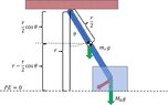
There will be an energy reduction due to the loss of vertical KE for the lower-bob mass. Apart from that we would need to know the materials involved, and the reason for this analysis.erobz said:I know its the impulse curve, but it has occurred to me that "how to model it" is a black box in my understanding.
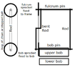
Will the lower-bob mass bounce ?
How deformable is the surface ?