Hall Sensor Output for Position of Rotor in BLDC Motor

  • Context: Engineering 
  • Thread starter Thread starter PhysicsTest
  • Start date Start date
  • Tags Tags
    Output Sensor
PhysicsTest
Messages
260
Reaction score
27
Homework Statement
I want to know the hall sensor output in a BLDC motor
Relevant Equations
Trapezoidal control of the BLDC motor
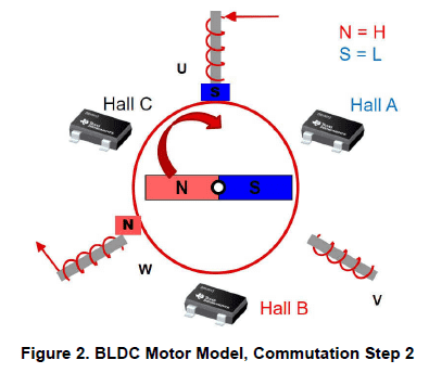
I wanted to understand the output of the hall sensor to detect the position of the rotor in the BLDC motor. The hall sensors are placed 120degrees apart. I downloaded one of the TI application notes and understanding it, and referring to the diagram
1673276502490.png

The rotor North and South is in a single straight line as per the diagram, now in this static condition what is the Hall A value does it read south pole? Hall B reads south or north pole? Please advise.
 

Attachments

Hall sensors A, B and C produce a 3-phase output that identifies the position of the rotor.
The output voltages from the sensors are amplified and digitized, to indicate if they are more North or South.
In your example; Hall A = South; Hall B = in transition; Hall C = North.
 
Yes the output of hall sensor will be 1 for North and 0 for South, but i don't understand when you say transition, because during power on i should know the Hall A, B, C output (from 1 to 5, 0 and 6 being invalid) to know the sector location.
 
In transition simply means the Hall sensor B has just switched, or is about to switch, (from North to South, if in clockwise rotation). It is a line-call on the diagram, you must actually read Hall sensor B to know which side of the line it is on. At power on, the motor may not yet be turning.
 

Similar threads

  • · Replies 13 ·
Replies
13
Views
2K
  • · Replies 5 ·
Replies
5
Views
3K
  • · Replies 4 ·
Replies
4
Views
2K
Replies
3
Views
7K
Replies
1
Views
8K
  • · Replies 19 ·
Replies
19
Views
11K
  • · Replies 2 ·
Replies
2
Views
8K
  • · Replies 2 ·
Replies
2
Views
4K
  • · Replies 4 ·
Replies
4
Views
9K