Using @Delta’s 'lumped model' approach (Post #2) we can treat the system as having 2 sources of emf – one generated by the loop left of PQ and the other generated by the loop right of PQ.
|Emf induced in left loop| = A|##\frac {dB}{dt}##| = 2*0.65² * 0.001 = 0.000845 V
|Emf induced in right loop| = A|##\frac {dB}{dt}##| = 0.65² * 0.001 = 0.0004225 V
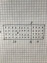
Applying Lenz’s law + right hand rule, the emfs’ polarities are as shown below.
Let R be the resistance of a 65cm length of wire (R = 0.065 Ω). We can represent the circuit as follows:
View attachment 288204
Kirchhoff’s 2nd law, left loop: 0.000845 + 0.065I₂ + 5*0.065I₁ = 0
Kirchhoff’s 2nd law, right loop: 0.0004225 + 3*0.065(I₁ – I₂) - 0.065I₂ = 0
Doing a bit of algebra and using an online ‘solver’ for simultaneous equations gives
I₂ = -0.000283A (so I guessed the direction of I₂ wrongly).