pkc111
- 224
- 26
- TL;DR
- Hi there,
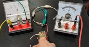
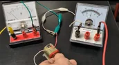
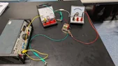
I have done an experiment measuring the voltage across the terminals of a dc motor, whilst running and then by holding it with my fingers to stop it. Done as demo for my high school class.
The voltage reading was higher when the motor was running, which was against my expectations as I thought the back-emf would have created a lower net voltage (being measured on the voltmeter on the motor terminals?).
So now I am guessing that the internal resistance of the motor is varying a
Hi there,
I have done an experiment measuring the voltage across the terminals of a dc motor, whilst running and then by holding it with my fingers to stop it. Done as demo for my high school class.
The voltage reading was higher when the motor was running, which was against my expectations as I thought the back-emf would have created a lower net voltage (being measured on the voltmeter on the motor terminals?).
So now I am guessing that the internal resistance of the motor is varying a lot to create this result?
Many thanks