Net torque about an axis through point A in a massless rod

AI Thread Summary
The discussion revolves around calculating net torque about an axis through point A on a massless rod. The initial calculations yield a net torque of 5.829 Nm, while the textbook states it should be 16.8 Nm, leading to confusion about the correct use of sine and cosine for the forces involved. Participants clarify that the horizontal component of the 10N force does not contribute to torque since it passes through the axis of rotation, and the correct approach involves using the sine of the angles based on their orientation relative to the axis. Ultimately, the correct net torque is confirmed as 16.8 Nm, with the importance of understanding force components emphasized. The discussion highlights the significance of accurately identifying the angles and components when calculating torque.
paulimerci
Messages
287
Reaction score
47
Homework Statement
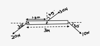
What is the net torque about an axis through point A?
Relevant Equations
Torque = F X d X sin theta
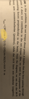
The net torque about an axis through point A is given by,
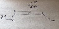
If I take the axis of rotation perpendicular to the paper and the solution I arrive would be the following below
Net torque = 30 cos45 x 1.5 - 10 cos30X 3
= 5.829Nm ( counterclockwise)

But the book gives an answer like this,
Net torque = 30 cos 45x1.5 - 10 x sin30 x 3 = 16.8Nm.What did I miss? It looks the horizontal component is perpendicular to the axis of rotation.
 

Attachments

  • Screen Shot 2022-11-16 at 12.22.59 PM.png
    Screen Shot 2022-11-16 at 12.22.59 PM.png
    8.3 KB · Views: 157
Physics news on Phys.org
The figure does not show where point A is.
 
I have updated the figure. Are you able to see it?
 
Are you sure?:
“10 cos30X 3”
 
Lnewqban said:
Are you sure?:
“10 cos30X 3”
because cosine component looks perpendicular to the axis of rotation. right?
 
paulimerci said:
It looks the horizontal component is perpendicular to the axis of rotation.
But that is not quite the right test. The horizontal component here passes through the axis of rotation, so cannot have any moment about it.
To find the moment a force exerts about an axis, you can either find the perpendicular distance from the line of action of the force to the axis or find the component of the force which is perpendicular to the line joining the point of application to the axis.

See https://www.physicsforums.com/insights/frequently-made-errors-mechanics-moments/
 
  • Like
Likes paulimerci and Lnewqban
paulimerci said:
because cosine component looks perpendicular to the axis of rotation. right?
67A32F68-35CA-41C4-9EA9-6AD782C3B6AD.jpeg
 
  • Like
Likes paulimerci and topsquark
Lnewqban said:
I think you are not grasping the error @paulimerci is making. It is true that the horizontal component of the 10N is perpendicular to the axis. Indeed, the whole of the 10N is because it lies in the plane perpendicular to the axis. As I wrote in post #6, that is the wrong test.
 
haruspex said:
But that is not quite the right test. The horizontal component here passes through the axis of rotation, so cannot have any moment about it.
To find the moment a force exerts about an axis, you can either find the perpendicular distance from the line of action of the force to the axis or find the component of the force which is perpendicular to the line joining the point of application to the axis.

See https://www.physicsforums.com/insights/frequently-made-errors-mechanics-moments/
okay if the axis of rotation is along the horizontal component I take the perpendicular component sin theta for 10N. How about 30N force, it looks sin theta perpendicular to the axis of rotation and I cannot use cosine for 30N?
 
  • #10
haruspex said:
I think you are not grasping the error @paulimerci is making. It is true that the horizontal component of the 10N is perpendicular to the axis. Indeed, the whole of the 10N is because it lies in the plane perpendicular to the axis. As I wrote in post #6, that is the wrong test.
Of course, you are correct.
The confusion comes from the different orientation of the angles.
Cosine works for one, but not for the other.

That was the intended hint in my diagram.
Perhaps @paulimerci can graphically see the error in “10 cos30X 3”.

Perpendicular or not to the axis of rotation, a force that has no lever respect to a point is unable to induce any moment on it.
 
  • #11
I still don't get it.
 
  • #12
paulimerci said:
I still don't get it.
What are the correct calculated values of the vertical and horizontal components of the 10N force?
Which one is able of induce a moment respect to pivot A?
 
  • #13
I got it right now, I was confused because the text book says cosine for 30 N force. That thing i still don't get it. As @haruspex said "To find the moment a force exerts about an axis, you can either find the perpendicular distance from the line of action of the force to the axis", I did that way and got the answer right.

Net torque at A = (30) (sin45)(1.5) - (10)(sin30)(3) = 16.8Nm
 
  • #14
paulimerci said:
I got it right now, I was confused because the text book says cosine for 30 N force. That thing i still don't get it.
What is “that thing”?
 
  • #15
Lnewqban said:
What is “that thing”?
I mean cosine for 30N in the textbook.
 

Attachments

  • Screen Shot 2022-11-16 at 4.43.42 PM.png
    Screen Shot 2022-11-16 at 4.43.42 PM.png
    25.6 KB · Views: 130
  • #16
paulimerci said:
the text book says cosine for 30 N force
For the 30N force the angle is 45o. For that angle, cos and sin have the same value.
 
  • #17
haruspex said:
For the 30N force the angle is 45o. For that angle, cos and sin have the same value.
I understand that but for what reason cosine is used there? What if some other angle was given?
 
  • #18
Isn't that cosine of 30N the middle vertical force represented and highlighted in the diagram of post #7 above?
 
  • #19
Lnewqban said:
Isn't that cosine of 30N the middle vertical force represented and highlighted in the diagram of post #7 above?
why is it taken as cosine if I take the axis of rotation along x axis? Why I'm not getting it?
 
  • #20
paulimerci said:
why is it taken as cosine if I take the axis of rotation along x axis? Why I'm not getting it?

The location and orientation of the angle the force makes with certain reference line is given in the problem, you need to decide which one to use, sine or cosine, according to what projection of the force you need to calculate.

Please, see:
https://www.mathsisfun.com/sine-cosine-tangent.html

http://zonalandeducation.com/mstm/physics/mechanics/forces/forceComponents/forceComponents.html

http://www.mem50212.com/MDME/MEMmods/MEM30005A/add_forces/add_forces.html
 
Last edited:
  • #21
paulimerci said:
I understand that but for what reason cosine is used there? What if some other angle was given?
Look carefully at the diagram. The angle marked as 45° is the angle between the force and the "vertical", whereas the angle marked 30° is between the force and the "horizontal".
 
  • #22
haruspex said:
Look carefully at the diagram. The angle marked as 45° is the angle between the force and the "vertical", whereas the angle marked 30° is between the force and the "horizontal".
Which component would you use for 30N? Sine or cosine?
 
  • #23
Lnewqban said:
The location and orientation of the angle the force makes with certain reference line is given in the problem, you need to decide which one to use, sine or cosine, according to what projection of the force you need to calculate.

Please, see:
https://www.mathsisfun.com/sine-cosine-tangent.html

http://zonalandeducation.com/mstm/physics/mechanics/forces/forceComponents/forceComponents.html

http://www.mem50212.com/MDME/MEMmods/MEM30005A/add_forces/add_forces.html
Is this how I have to choose the reference line? see the picture below
 

Attachments

  • Screen Shot 2022-11-17 at 1.28.31 PM.png
    Screen Shot 2022-11-17 at 1.28.31 PM.png
    89.9 KB · Views: 104
  • #24
paulimerci said:
Which component would you use for 30N? Sine or cosine?
Call the two marked angles ##\alpha=45°## and ##\beta=30°##.
In each case, the line joining the point of application of force to the axis of rotation is horizontal in the diagram, so we want the component of force that's vertical. To find the component in a given direction we use the cosine of the angle between the two.
##\alpha## is the angle the force makes to the vertical, so we use ##\cos(\alpha)=\cos(45°)##.
##\beta## is the angle the force makes to the horizontal, so we use ##\cos(90°-\beta)=\sin(\beta)=\sin(30°)##
 
  • Like
Likes topsquark and paulimerci
  • #25
haruspex said:
Call the two marked angles ##\alpha=45°## and ##\beta=30°##.
In each case, the line joining the point of application of force to the axis of rotation is horizontal in the diagram, so we want the component of force that's vertical. To find the component in a given direction we use the cosine of the angle between the two.
##\alpha## is the angle the force makes to the vertical, so we use ##\cos(\alpha)=\cos(45°)##.
##\beta## is the angle the force makes to the horizontal, so we use ##\cos(90°-\beta)=\sin(\beta)=\sin(30°)##
I really forgot to use this basic trigonometric ratios of complimentary angles. Thank you so much @haruspex ! Now I understand how we get cosine for 30N.
 
  • #26
Am I missing something? The rod is "massless" and is subject to a net force (and torque too) The dynamics might be tricky.
 
  • #27
hutchphd said:
Am I missing something? The rod is "massless" and is subject to a net force (and torque too) The dynamics might be tricky.
Well spotted, but I would guess it is a typo for "massive"
 
  • #28
haruspex said:
Well spotted, but I would guess it is a typo for "massive"
No, in the textbook it says massless rod.
 
  • #29
paulimerci said:
No, in the textbook it says massless rod.
Then I guess they just didn’t want the student to add mg.
 
  • #30
paulimerci said:
Is this how I have to choose the reference line? see the picture below
Sorry, I have no idea about what you are trying to represent in that picture.

The original question only refers to “the net torque about an axis through point A”.
There is no reference line to represent or discuss, I believe.

Sorry to ask, but how can you be still confused about this problem after studying the links provided in post #20 above?
 
  • #31
I’m not confused, I thought the reference line represents an arbitrary fixed line (as an x-axis or a polar axis) from which coordinates of a point are computed.
 
  • #32
paulimerci said:
I’m not confused, I thought the reference line represents an arbitrary fixed line (as an x-axis or a polar axis) from which coordinates of a point are computed.
Sorry, I misunderstood your picture.

BEA3AE8C-7F2F-4B0D-9027-C26087594271.jpeg
 
  • #33
paulimerci said:
I’m not confused, I thought the reference line represents an arbitrary fixed line (as an x-axis or a polar axis) from which coordinates of a point are computed.
Another way to look at the angle problem is to write the torque equation as ##\tau = \textbf{F} \times \textbf{d}##. The magnitude of the torque will be ##\tau = F d ~ sin( \theta )## where the angle is between and measured counterclockwise. To do this draw a quick sketch and place the tails of d and F at the same point.

-Dan
 
  • Like
Likes paulimerci and Lnewqban
  • #34
paulimerci said:
I’m not confused, I thought the reference line represents an arbitrary fixed line (as an x-axis or a polar axis) from which coordinates of a

Lnewqban said:
Sorry, I misunderstood your picture.

View attachment 317371
Thank you!
 
Back
Top