
Frequently Made Errors in Mechanics: Moments
Table of Contents
Entire List for Frequently Made Errors Series
Mechanics
Other
The term “moment” is used in various ways in Physics and Mathematics:
- Given a force and a reference point, the force has a moment (or torque) about the point.
- A rigid body has moments of mass of various orders (zeroth, first, second..)
- Similarly, moments of area, and moments of statistical distributions
This page only concerns the moment of a force and moment of inertia (= second moment of mass).
1. Magnitude of Torque
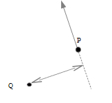
X “The magnitude of the moment of a force applied at a point P about a point Q is the magnitude of the force multiplied by the distance from P to Q”
In vectors, if the force vector is F, and r is the vector from Q to P then the moment is the vector ##\vec r \times \vec F##. (Note that the order is important, but the precise point P is not; it can be anywhere in the line of action.)
In terms of scalars, there are three ways we can say this:
- ✓ The magnitude of the torque about a point Q is the magnitude of the force, multiplied by the perpendicular distance from Q to the line of action of the force.

- ✓ The magnitude of the torque about a point Q is the distance from Q to the point of application of the force, P, multiplied by the magnitude of the component of the force perpendicular to the line QP.

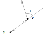
- ✓ The magnitude of the torque about a point Q is the magnitude of the force, multiplied by the distance from Q to any point, P, in the line of application of the force, multiplied by the sine of the angle between QP and the line of action of the force.

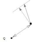
If ##\vec r## is given in terms of perpendicular co-ordinates, it may be more convenient to resolve the force into corresponding perpendicular forces and find the moment from each separately.

The moment of ##\vec F_2## about P is ##F_{2x} r_{2y} + F_{2y} r_{2x}## anticlockwise.
Tip: If there are forces involved that are neither known nor required in the answer, by taking moments about the point where their lines of action intersect you may be able to simplify the working.
Example 1: “A uniform beam weight W length 2L rests on supports A and B, at a distance a from the left end and B from the right end respectively. What is the normal force the beam exerts at A?”
We could look at the vertical force balance
$$W = N_A + N_B$$
and take moments about anywhere, e.g. at the left end of the beam:
$$W L = N_A a + N_B (2L – b)$$
and solve. But since we only wish to find ##N_A##, we can get there with one equation, taking moments about B:
$$W (L – b) = N_A (2L – b – a)$$
Example 2: “A uniform solid ball starts with speed v, not rotating, along a horizontal floor. The coefficient of kinetic friction between ball and floor is ##\mu_k##. What is the linear speed of the ball when it commences rolling?”
Since friction acts along the floor, we can obviate the need to determine the frictional force by taking moments about a point in the path on the floor. The initial angular momentum of the ball about the point is ##m v r##.
By the parallel axis theorem, the moment of inertia of the rolling ball about its point of contact with the floor is ##I_{\mathrm{CoM}} + m r^2 = \frac{7}{5} m r^2##. If the final linear speed is ##u## then the final angular momentum of the ball about the point is ##\frac{7}{5} m r^2 \frac{u}{r} = \frac{7}{5} m u r##.
Since the net moment of all forces about that point is zero (gravity and normal force cancel), ##\frac{7}{5} m u r = m v r##, thus ##u = \frac{5}{7} v##.
2. Couples
A couple is a pair of forces acting on a body that is equal and opposite as vectors but with different lines of action. There is no net force, but there is a net torque.
In this case, only, the torque is the same about every point.
Such a torque is sometimes referred to as a screw; others use ‘couple’ to mean either a pair of forces or their net torque.
3. Equivalent Systems of Forces
A system of forces in two dimensions can be fully represented by either a single force (their vector sum, with a suitable line of action) or a screw.
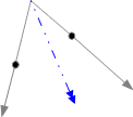
- Suppose forces ##\vec{F_1}, \vec{F_2}## act on a body, and their lines of action intersect at point P. The pair is equivalent to a force ##\vec F = \vec{F_1} + \vec{F_2}## acting through P.
Repeating this procedure, we can reduce any system to only parallel forces.
- Suppose two parallel forces, which are not equal and opposite, act on a body. The pair is again equivalent to a single force:


The line of action of the equivalent single force is such that if you pick a point in it then the pair ##\vec{F_1}, \vec{F_2}## has no net moment about that point. Its distances from the other two lines of action are in inverse proportion to the magnitudes of the forces.
Repeating this procedure, we can reduce any system of parallel forces to either a single force or a pair of parallel equal and opposite forces (a screw).
In three dimensions, any system of forces acting on a body can be represented by a single force plus a screw parallel to the force.
4. Joints
Some confusion may arise regarding the directions forces act at joints.
At a freely rotating joint in a static arrangement, there is no torque exerted, but the reaction force can be in any direction.
“In the diagram, angle ADB=angle BDA=30 degrees. Links CD and BC are considered massless. ADO+wheel has weight W and mass center G. Write out the force equations on ADO, taking moments about A.”

Attempted solution:
X Perpendicular to AD, ##F_{CD} \cos(30^\circ) = W \sin(30^\circ) ##
The force on AD at joint A need not be purely along AD. Indeed, it cannot be. Taking moments about D, W has a clockwise moment. This must be balanced by a moment from the force at A.
On the other hand, because CD is considered massless, the force CD exerts at D and C is along CD.
In a more complicated arrangement, a single rigid strut may have several joints. At each joint, the forces at the other joints have balancing moments.
5. Reference Frames
In applying the torque/angular acceleration equation ##\vec F \times \vec s = \tau = I \vec{\alpha}##, or the law of conservation of angular momentum, the reference point for taking moments should normally be fixed relative to an inertial frame. But other choices can be valid.
For a mass element ##dm## at ##\vec r## in a fixed reference frame O, torque is ##d\tau = \vec r \times \ddot{\vec r}\,dm##.
So ##\tau = \int \vec r \times \ddot{\vec r}\,dm##.
If we now allow the reference point an acceleration ##\vec a## then
$$\tau’ = \int \vec r \times (\ddot{\vec r} – \vec a)\,dm = \tau – \left(\int \vec r\,dm\right)\times \vec a$$
$$\int \vec r\,dm = M \hat{\vec r}$$, where ##M## is the mass of the body and ##\hat{\vec r}## is the position of its mass centre in the reference frame.
Therefore ##\tau’ = \tau – M \hat{\vec r} \times \vec a##.
##\tau’ = \tau## if:
- O is the mass centre (##\hat{\vec r} = 0##), or
- ##\vec a = 0##, or
- the acceleration is along the line to the mass centre, ##\vec a \parallel \hat{\vec r}##
Each of the following is valid, for example:
- Any point that remains stationary
- The mass centre of the body
- The point in the body is the instantaneous center of rotation.
Example: “A uniform rod length 2L, mass M, lying on a smooth table is struck perpendicularly at one end by a clay lump mass m moving at speed u. The clay adheres to the stick. Find the angular speed of the rod just after impact.”
Let the angular speed after impact be ##\omega## and the linear speed of the mass center of the rod be ##v##.
Moment of inertia of the rod about its center = ##I = \dfrac{M L^2}{3}##.
Sign convention: clay hits the right-hand end of the rod from its perspective, rotation to the left is positive.
By conservation of linear momentum, ##m u = (M + m) v + m L \omega##
A Taking angular momentum about the point in space where the clay hit the rod: Prior angular momentum of rod = prior angular momentum of clay = 0. Posterior a.m. of rod = ##I \omega – M v L##. Posterior angular momentum of clay = 0. ##\omega = \dfrac{M v L}{I} = \dfrac{3 v}{L}##. Combining with the linear momentum equation gives ##\omega = \dfrac{3 m u}{L (M + 4 m)}##. B Taking angular momentum about the mass centre of the rod (a non-inertial frame): Prior angular momentum of rod = 0. Prior angular momentum of clay = ##m u L##. Posterior a.m. of rod = ##I \omega##. Posterior a.m. of clay = ##m L^2 \omega##. So ##m u L = \omega (I + m L^2) = \omega \left(\dfrac{M L^2}{3} + m L^2\right)##, giving ##\omega = \dfrac{3 m u}{L (M + 3 m)}##.
6. Parallel Axis Theorem
X “If the moment of inertia of a body mass M about a given axis is I, then its MoI about a parallel axis distance a from the first is ##I+Ma^2##”
✓ “If the moment of inertia of a body mass M about a given axis through its mass center is I, then its moment about a parallel axis distance a from the first is ##I + M a^2##”
Example:
“A rigid object S, mass M, is formed from two lumps connected by a light rod length L. The mass center of S is distance x along the rod from lump A. If the moment of inertia of S about an axis through the ‘A’ end of the rod is ##I_A##, what is it about a parallel axis through the other end of the rod?”
MoI about the mass centre = ##I_{\text{CoM}} = I_A – M x^2##
MoI about the B end = ##I_B = I_A – M x^2 + M (L – x)^2 = I_A + M L (L – 2 x)##
Masters in Mathematics. Interests: climate change & renewable energy; travel; cycling, bushwalking; mathematical puzzles and paradoxes, Azed crosswords, bridge


[QUOTE="vanhees71, post: 5498822, member: 260864"]ne should also note that the tensor of inertia, JAJ_A, must refer to the body-fixed point AA.”sure
[QUOTE="vanhees71, post: 5498822, member: 260864"]ne should also note that the tensor of inertia, JAJ_A, must refer to the body-fixed point AA.”sureaccidentally I came across an articlehttps://www.jstor.org/stable/2973359?seq=1#page_scan_tab_contentsperhaps It should be noted about a general formula. Let a point ##A## be any point of the rigid body. Then$$J_Adot{boldsymbolomega}+boldsymbolomegatimes J_Aboldsymbolomega+mboldsymbol{AS}times boldsymbol a_A=boldsymbol M_A;$$where ##S## is the center of mass, ##m## is the mass of the rigid body, ##boldsymbol a_A## is the acceleration of the point ##A##.
One should also note that the tensor of inertia, ##J_A##, must refer to the body-fixed point ##A##.
Nice article. I just want to add some comment on the torque equation for rigid body and on some very frequent errors that arise in this regard. The equation of torque is $$J_Adot{boldsymbol omega}+[boldsymbolomega,J_Aboldsymbolomega]=boldsymbol M_A.qquad (*)$$ Here ##J_A,boldsymbolomega## are the operator of inertia about the point ##A## and the angular velocity of the rigid body respectively; ##boldsymbol M_A## is the torque applied to the rigid body. But what is the point ##A##? If ##A## is a stationary point of the rigid body or its center of mass then equation (*) is correct.In general, it is incorrect to use formula (*) for ##A## to be instantaneous centre of rotation.Another frequent error is concerned to the term ##[boldsymbolomega,J_Aboldsymbolomega]##. This term is equal zero identically in planar problems. But one can not forget it in essentially 3D problems.
Nice post, Haruspex. I’ll have to come back to this when I start my physics and mechanics classes.
Having read this, my future calcs involving torques and moments of inertia will be much faster and easier.
Nice work haruspex!