Phasor Diagram of No Load Ideal Transformer

Join the discussion
Registration is free. Start your own thread to ask a follow-up.
2 replies · 19K views
samieee
Messages
67
Reaction score
0
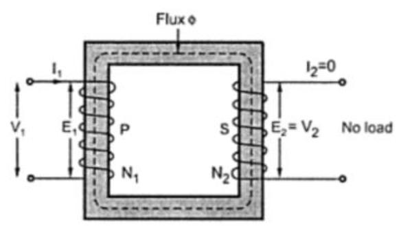
For a no load ideal transformer

vufGi.jpg


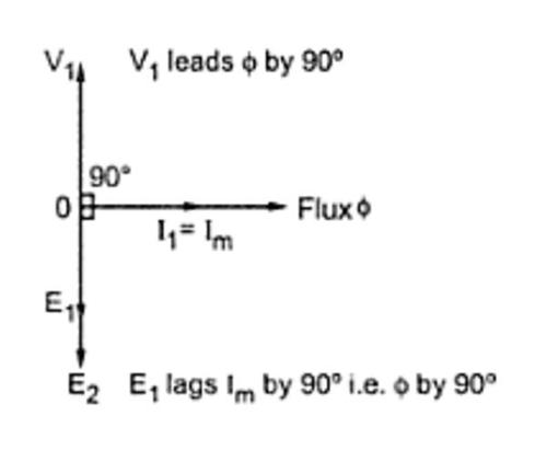
V1 is anti phase with E1?

wnvOP.jpg


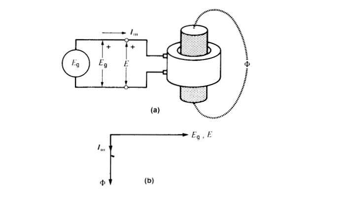
or

in phase like this?

1EyPP.png
 
Engineering news on Phys.org
I have seen both types of phasor diagram in different books. But the first one is the accurate answer, I think. Because of Lenze's law.
 
It'll help you visualize the problem if you redraw the top figure to place both coils on same side of the core.

Make both coils less tall and move your secondary over to other side so it's just above the primary,
paying careful attention to preserve which direction the turns are wound.