Problem with SPICE calculation of the ripple in half-wave rectifier

Click For Summary

Discussion Overview

The discussion revolves around discrepancies in ripple voltage calculations for a half-wave rectifier using SPICE simulation compared to theoretical calculations. Participants explore the implications of circuit parameters, including resistance and capacitance, on the ripple voltage observed in simulations versus calculations.

Discussion Character

  • Technical explanation
  • Debate/contested
  • Mathematical reasoning

Main Points Raised

  • One participant notes a difference in ripple voltage between SPICE simulation (31mV) and their theoretical calculation (38mV), questioning the accuracy of the simulation.
  • Another participant suggests that the high series resistance in the power supply affects the capacitor's charge and discharge times, leading to a different measured ripple voltage.
  • A participant provides detailed calculations for ripple voltage, including the effects of discharge time and average current, indicating a small difference attributed to diode switching times.
  • One participant reflects on their initial theoretical calculations, acknowledging they were based on an approximate formula and suggests a more complete formula that includes generator resistance and equivalent series resistance of the capacitor.
  • Another participant mentions that the formula used is conservative and typically includes a safety margin, implying that it may not always yield the most accurate results.
  • A cleaned-up schematic is shared, which is claimed to run faster and measure ripple more accurately over multiple cycles.

Areas of Agreement / Disagreement

Participants express differing views on the accuracy of their calculations and the implications of circuit parameters on ripple voltage. There is no consensus on the correct approach or formula to use, and the discussion remains unresolved regarding the best method for calculating ripple voltage in this context.

Contextual Notes

Participants highlight potential limitations in their calculations, including assumptions about resistance and the use of approximate formulas. The discussion reflects varying interpretations of circuit behavior and the impact of component characteristics on simulation results.

Gio47818732
Messages
3
Reaction score
1
TL;DR
spice does show a different ripple voltage than the one calculated using spice I load or Vdc load and Req and C
spice shows a ripple voltage of about 31mV, but calculating the ripple with the formula i get 38mV wich is really weird.
spice does show a different ripple voltage than the one calculated using spice I load or Vdc load and Req and C.
spice shows a ripple voltage of about 31mV, but calculating the ripple with the formula i get 38mV which is really weird.

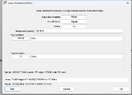
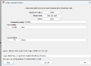
as you can see in the photo i get a dc output voltage of around 3.511 which divided by (Req*C*f) gives me 38mV. Spice tho shows me in output a ripple voltage measured of around 31mV which makes no sense since formula is ripple voltage=Vdc/(Req*C*f) since capacitance equivalent impedence is supposed to be 0. also if that even counted that should increase the ripple voltage instead of giving me a ripple voltage smaller by 7mV than the calculated one.

thank you for the answers.

Screenshot 2024-12-09 161253.png
 

Attachments

  • Screenshot 2024-12-09 161306.png
    Screenshot 2024-12-09 161306.png
    16.8 KB · Views: 53
  • Screenshot 2024-12-09 161749.png
    Screenshot 2024-12-09 161749.png
    24 KB · Views: 66
  • Screenshot 2024-12-09 161844.png
    Screenshot 2024-12-09 161844.png
    24.1 KB · Views: 54
Last edited by a moderator:
Engineering news on Phys.org
Welcome to PF.

I know it is a simple schematic file.asc, but there is critical embedded detail that does not show in screenshots. Please attach your LTspice file.asc to your next post so I can run the simulation.

You will need to change the extension from file.asc to file.txt, or make it file.asc.txt so it can be attached to your post.
 
  • Like
Likes   Reactions: Gio47818732
here the schematic, sorry i didn't add it before
 

Attachments

  • Like
Likes   Reactions: Baluncore
You have a high series resistance 50R0 in the power supply. The capacitor charge time, (or phase angle), is therefore longer than expected, so the discharge time is proportionally less. I measure the discharge time, dt, to be 823.5 us, NOT the 1000 us you may assume.
C = Q / v ; The definition of capacitance.
C = i * t / v ;
C = i * dt / dv ;
dv = i * dt / C = ripple voltage.

Your LTspice .meas directive results in:
vripple: PP(v(n002))=0.031065 FROM 0 TO 0.05
vdc_out_load: AVG(v(n002))=3.51168 FROM 0 TO 0.05

C = 47.8 uF
Requ = 1.923 k
Average i discharge, is AVG(Vout) / Requ
dv = i * dt / C= ( 3.51168 / 1k923 ) * 823u5 / 47u8 = 0.03146 V
The 0.4 mV difference is to do with the switch on and off times of the diode, and my ability to put a cursor on a pixel.

You need to revise your approach to the computation of the ripple voltage.

Label your nodes, so the automatic numbering does not change your .MEAS directive node when the circuit changes.

Do not include the units in spice, only the multiplier.
Replace the decimal point with the multiplier on schematics.
20 ms = 20.0 m = 20m0 .
A one farad capacitor, 1F , is only one femtofarad in SPICE.
 
  • Like
Likes   Reactions: Gio47818732, DaveE and berkeman
thanks for the headups, they made me rethink my approach to the problem and made me realize things i didn't before when using spice; also going back to my theorical calculations of the ripple it seems they were also off due to me using the approximated to the first order formula for the ripple , the complete formula not including the generator resistance would have been (V-Von)*(1-exp(-(T-T{it takes to charge the condensator})/(R{equivalent}*C))).
where V-Von is the dc current i measure in out, also if we consider the equivalent series resistance of the condensator in case it matters we would need to add R_{of the capacitance}*(V-Von)/(R{equivalent}.
Correct me if i am wrong,i just wrote it in case someone has my same problem and forgets they are using the approximate formula instead of the complete one
 
The formula you used, works well for a conservative design, in that under most circumstances, it included a safety margin.

Attached is a cleaned-up schematic, that runs faster and sufficiently accurately. It measures ripple over two cycles at the end of the transient analysis.

Draft30-1.png
 

Attachments

Similar threads

  • · Replies 6 ·
Replies
6
Views
2K
  • · Replies 7 ·
Replies
7
Views
2K
Replies
5
Views
27K
Replies
4
Views
3K
  • · Replies 4 ·
Replies
4
Views
4K
  • · Replies 2 ·
Replies
2
Views
3K
  • · Replies 5 ·
Replies
5
Views
4K
  • · Replies 8 ·
Replies
8
Views
8K
  • · Replies 8 ·
Replies
8
Views
3K
Replies
1
Views
3K