artis
- 1,479
- 977
I thought about this for some time but I can't seem to really understand the cause.
Now I remember some time ago using a transformer for my self made soldering iron, I wound it to have the right temperature at about 45 VAC input but I guess I missed a bit , so that when I connected it to the 45 v output of my transformer it was hot but not hot enough for some higher temp. tin.
What came to mind was to rectify and smooth the AC output to DC, I did this and indeed the soldering iron was now just hot enough to melt all kinds of tin.
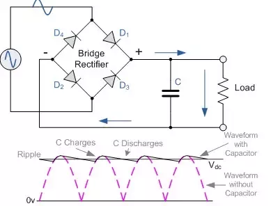
Clearly rectifying AC doesn't increase it's voltage or maximum power , by adding a filter capacitor I can just simply "catch" the AC peak voltage which is the AC RMS voltage times 1.414, so for 45 VAC the peak DC rectified voltage is then about 63 volts.So just out of curiosity I did a second experiment , this time deliberately. I took a resistive heating element (an old heater essentially) and one of my test transformers. It has both an AC output as well as a full bridge rectifier with filter caps, so I can also use the rectified but unfiltered DC or the rectified and filtered DC.
So my results are as follows.
1) Secondary AC output with no load (RMS value measured by multimeter) = 100 VAC which implies the AC peak should be 140 VAC.
2) Rectified but unfiltered DC output after the bridge rectifier with no load = about 95/97 volts , some drop due to diode forwards voltage drop (older model diodes)
3) And finally the no load filtered DC output = 140 VDCHere is the part I don't quite understand. As I connect the heating element as my load I now measure the amps flowing to the heater.
1) Heater on AC draws about 1.03A at 98 VAC (about 2-3 volts drop due to load)
2)Heater on unfiltered rectified DC draws about 0.903 A at about 93/94 volts , again few volts drop in the transformer and in the diodes.
3) Heater on rectified and filtered DC draws 1.3A at about 130 VDC. (10 volt drop from maximum 140 VDC due to load)
So here is my dilemma, clearly I can push more amperes through a resistor by rectifying and filtering my AC instead of just using the AC as is. But what I don't understand is this, the bridge rectifier nor the capacitor doesn't add any power to the circuit, all the power comes from the transformer secondary as is. The capacitor simply charges to the peak of the sine wave during each half period.
The question is why isn't this sine wave peak manifesting as current/heat in the resistor on AC but only after rectification to DC and filtering?
A resistor is said to be 100% efficient as it turns current into heat, the current through a fixed resistance is proportional to voltage, so taking the AC RMS voltage one can see it's lower than the rectified and filtered DC but the DC maximum voltage is then again just the AC peak, so why isn't this AC peak heating the resistor when it's connected to AC ?
Now I remember some time ago using a transformer for my self made soldering iron, I wound it to have the right temperature at about 45 VAC input but I guess I missed a bit , so that when I connected it to the 45 v output of my transformer it was hot but not hot enough for some higher temp. tin.
What came to mind was to rectify and smooth the AC output to DC, I did this and indeed the soldering iron was now just hot enough to melt all kinds of tin.
Clearly rectifying AC doesn't increase it's voltage or maximum power , by adding a filter capacitor I can just simply "catch" the AC peak voltage which is the AC RMS voltage times 1.414, so for 45 VAC the peak DC rectified voltage is then about 63 volts.So just out of curiosity I did a second experiment , this time deliberately. I took a resistive heating element (an old heater essentially) and one of my test transformers. It has both an AC output as well as a full bridge rectifier with filter caps, so I can also use the rectified but unfiltered DC or the rectified and filtered DC.
So my results are as follows.
1) Secondary AC output with no load (RMS value measured by multimeter) = 100 VAC which implies the AC peak should be 140 VAC.
2) Rectified but unfiltered DC output after the bridge rectifier with no load = about 95/97 volts , some drop due to diode forwards voltage drop (older model diodes)
3) And finally the no load filtered DC output = 140 VDCHere is the part I don't quite understand. As I connect the heating element as my load I now measure the amps flowing to the heater.
1) Heater on AC draws about 1.03A at 98 VAC (about 2-3 volts drop due to load)
2)Heater on unfiltered rectified DC draws about 0.903 A at about 93/94 volts , again few volts drop in the transformer and in the diodes.
3) Heater on rectified and filtered DC draws 1.3A at about 130 VDC. (10 volt drop from maximum 140 VDC due to load)
So here is my dilemma, clearly I can push more amperes through a resistor by rectifying and filtering my AC instead of just using the AC as is. But what I don't understand is this, the bridge rectifier nor the capacitor doesn't add any power to the circuit, all the power comes from the transformer secondary as is. The capacitor simply charges to the peak of the sine wave during each half period.
The question is why isn't this sine wave peak manifesting as current/heat in the resistor on AC but only after rectification to DC and filtering?
A resistor is said to be 100% efficient as it turns current into heat, the current through a fixed resistance is proportional to voltage, so taking the AC RMS voltage one can see it's lower than the rectified and filtered DC but the DC maximum voltage is then again just the AC peak, so why isn't this AC peak heating the resistor when it's connected to AC ?