Shear lines from a FBD with distributed forces

In summary, the conversation discusses a problem involving determining the functions for the Shear and Moment lines for the half-wing of an airliner. The problem also involves creating a complete FBD for each required separation. The teacher mentions that working from wingtip to wing root is not mandatory and working from root to tip may be easier.
  • #1
Finn072
3
0
Homework Statement
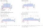
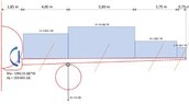
Formulate both the V and M diagrams for the following FBD.
Relevant Equations
How would I go about this? I've looked everywhere on youtube but couldn't find a single example that used distributed forces.
, this is the FBD in question
 
Physics news on Phys.org
  • #2
Welcome!
I still can’t see the posted image.
 
  • #3
Lnewqban said:
Welcome!
I still can’t see the posted image.
Hey thanks! this should work:
I'll also add my attempt at the 4 V(m) lines and the resultant graph (which isn't correct, I do know that much)
 

Attachments

  • shears.png
    shears.png
    30.7 KB · Views: 51
  • fbd.jpg
    fbd.jpg
    17.1 KB · Views: 58
  • #4
Could you post the text of the problem?
It seems to be the load distribution on the half-wing of an airliner.
 
  • #5
Lnewqban said:
Could you post the text of the problem?
It seems to be the load distribution on the half-wing of an airliner.
"Determine the functions for the Shear and Moment (“V & M”) lines and put these functions in a table. Choose x=0 at the wingtip, then start working from the wingtip to the wing root. Consequently use the right section of a separation. Create a complete FBD for each required separation."

My teacher mentioned during a lesson that working from tip to root was not mandatory, since the opposite is easier (apparently)
 

What are shear lines from a FBD with distributed forces?

Shear lines from a FBD (free body diagram) with distributed forces are lines that represent the distribution of shear forces along a structure. They are used to analyze the internal forces and stresses within a structure.

How are shear lines determined from a FBD with distributed forces?

Shear lines are determined by plotting the distribution of shear forces along the length of a structure. This can be done by breaking the structure into smaller sections and calculating the shear forces at each section.

What information can be obtained from shear lines?

Shear lines provide information about the distribution of shear forces along a structure, which can be used to determine the maximum shear force and the location of points of zero shear. They can also be used to analyze the stability and strength of a structure.

What factors affect the shape of shear lines?

The shape of shear lines is affected by the magnitude and distribution of the applied forces, as well as the geometry and material properties of the structure. Changes in any of these factors can result in different shapes and patterns of shear lines.

How can shear lines be used in structural design?

Shear lines are an important tool in structural design as they help engineers determine the appropriate size and placement of structural elements to withstand the shear forces acting on a structure. They can also be used to identify potential weak points in a structure and inform design modifications to improve its strength and stability.

Similar threads

  • Introductory Physics Homework Help
Replies
7
Views
1K
  • Introductory Physics Homework Help
Replies
6
Views
917
  • Introductory Physics Homework Help
Replies
16
Views
603
  • Introductory Physics Homework Help
Replies
13
Views
3K
  • Introductory Physics Homework Help
Replies
24
Views
1K
  • Introductory Physics Homework Help
Replies
5
Views
813
  • Introductory Physics Homework Help
Replies
7
Views
1K
  • Introductory Physics Homework Help
Replies
5
Views
461
Replies
17
Views
982
  • Introductory Physics Homework Help
Replies
15
Views
3K
Back
Top