Simulation of transistor switch circuit

Join the discussion
Ask a follow-up here, or get your own question answered by working scientists, mathematicians and engineers — people, not an autocomplete.
Real named experts · corrections over time · the nuance an AI answer skips
5 replies · 4K views
Alex Hughes
Messages
54
Reaction score
13
Hello, I'm new to electronics and I'm reading a book currently to learn more about the topic. I'm currently on a section where I'm building circuits where I'm using a transistor as a switch. I decided to experiment with the circuit they gave me and put it in a simulation software called Proteus. Here it is.
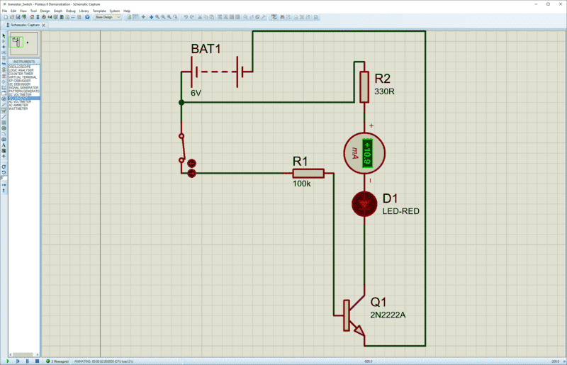
upload_2018-3-21_11-1-29.png


There was one thing I was confused on. In the book it told me I can calculate the current across the LED by taking 6V - 1.8 (voltage drop across the LED) and dividing it by the 330Ohm resistor. When they did this they got 12.7mA. However according to the simulation, if you look at the ammeter it reads 10.9mA. Why is this? I also went to calculate the Vce (voltage across the collector and emitter of the transistor) using the KVL method. I calculated the voltage from the source - the voltage drop across the resistor (330*0.0127) and the voltage drop across the LED and set it equal to Vce. This gave me Vce = 6 - (330*0.0127) - 1.8 which equals 9mV. This seems very low to me but doesn't this make sense because if the transistor is in saturation the voltage across the collector and emitter should be really close to 0 right? Lastly, when I took a voltmeter across the collector and emitter in the simulation I got 0.58V. Can somebody tell me if either me or the simulation is screwing up here. I also made sure to set the voltage drop of my LED to 1.8V in the simulation, so that's not the issue. Please help, this is really bothering me.
 

Attachments

  • upload_2018-3-21_11-1-29.png
    upload_2018-3-21_11-1-29.png
    23 KB · Views: 1,620
Engineering news on Phys.org
OK, I am beginner when it comes to these things as well, so I can be off, but have you tried to change R1 to 10k, or even 1k? You are driving 2N2222 with just 60 μA, that can be not enough (β is listed as up to 300, but depending on conditions can start at much lower values, 100 would produce 6 mA though the LED).
 
  • Like
Likes   Reactions: davenn
Alex Hughes said:
Hello, I'm new to electronics and I'm reading a book currently to learn more about the topic. I'm currently on a section where I'm building circuits where I'm using a transistor as a switch. I decided to experiment with the circuit they gave me and put it in a simulation software called Proteus. Here it is.

View attachment 222458

There was one thing I was confused on. In the book it told me I can calculate the current across the LED by taking 6V - 1.8 (voltage drop across the LED) and dividing it by the 330Ohm resistor. When they did this they got 12.7mA.

That method ignores the Vcesat of the transistor. So it's just an approximation.
However according to the simulation, if you look at the ammeter it reads 10.9mA. Why is this?

That probably does take into account Vcesat.
I also went to calculate the Vce (voltage across the collector and emitter of the transistor) using the KVL method. I calculated the voltage from the source - the voltage drop across the resistor (330*0.0127) and the voltage drop across the LED and set it equal to Vce. This gave me Vce = 6 - (330*0.0127) - 1.8 which equals 9mV. This seems very low to me but doesn't this make sense because if the transistor is in saturation the voltage across the collector and emitter should be really close to 0 right?

You used 12.7mA (which is the current calculated by ignoring Vcesat) to try and calculate Vcesat. So obviously it will be zero.
Lastly, when I took a voltmeter across the collector and emitter in the simulation I got 0.58V. Can somebody tell me if either me or the simulation is screwing up here. I also made sure to set the voltage drop of my LED to 1.8V in the simulation, so that's not the issue. Please help, this is really bothering me.

The simulation is probably correct.

More later when I get home.
 
  • Like
Likes   Reactions: berkeman
Ok I'm back home..

Alex Hughes said:
There was one thing I was confused on. In the book it told me I can calculate the current across the LED by taking 6V - 1.8 (voltage drop across the LED) and dividing it by the 330Ohm resistor. When they did this they got 12.7mA

As I said above that method ignores Vcesat so is just an approximation. It's quite a reasonable thing to do because Vcesat is small compared to the 6V supply voltage and LEDs don't care much about the exact current.

If we want to do things more accurately...

Vcesat can vary depending on the transistor so here is the/a data sheet for the 2N2222A...

http://web.mit.edu/6.101/www/reference/2N2222A.pdf

It gives two values for the Collector−Emitter Saturation Voltage (Vcesat) depending on the base and collector current...

The data sheet says that with IC = 150 mAdc and IB = 15 mAdc, Vcesat will be a maximum of 0.3V. This is lower then the value the simulator gave you (0.58V) probably because your base current is a lot lower so the transistor in your circuit is ON but not as much as it could be (as Borek said). I will use 0.58V in the following calculations...

So the correct method/equation for calculating the current in the LED would be

I = (Vcc - Vd - Vcesat)/ R
= (6 - 1.8 - 0.58)/330
= 10.9mA

This is exactly what the simulator made it confirming that the difference between 12.7mA and 10.9mA is down to the inclusion of Vcesat in the equation or not.

In the real world electronic components like transistors and resistors vary a lot due to manufacturing tolerances. These sometimes have a greater effect on the result than the inclusion or omission of Vcesat. In practice the LED will work just fine with either current so the approximation is reasonable.
 
Last edited:
  • Like
Likes   Reactions: berkeman and Alex Hughes
If you want to experiment try changing the value of R1 to 330 Ohms. That would increase the base current to around

Ib = (Vcc - Vd)/R1 = (6-0.7)/330 = 16mA

That would turn the transistor on harder and should lower the Vcesat from 0.58 to below the datasheet value of 0.3V (assuming the model of the transistor is accurate).
 
  • Like
Likes   Reactions: Alex Hughes
CWatters said:
Ok I'm back home..
As I said above that method ignores Vcesat so is just an approximation. It's quite a reasonable thing to do because Vcesat is small compared to the 6V supply voltage and LEDs don't care much about the exact current.

If we want to do things more accurately...

Vcesat can vary depending on the transistor so here is the/a data sheet for the 2N2222A...

http://web.mit.edu/6.101/www/reference/2N2222A.pdf

It gives two values for the Collector−Emitter Saturation Voltage (Vcesat) depending on the base and collector current...

The data sheet says that with IC = 150 mAdc and IB = 15 mAdc, Vcesat will be a maximum of 0.3V. This is lower then the value the simulator gave you (0.58V) probably because your base current is a lot lower so the transistor in your circuit is ON but not as much as it could be (as Borek said). I will use 0.58V in the following calculations...

So the correct method/equation for calculating the current in the LED would be

I = (Vcc - Vd - Vcesat)/ R
= (6 - 1.8 - 0.58)/330
= 10.9mA

This is exactly what the simulator made it confirming that the difference between 12.7mA and 10.9mA is down to the inclusion of Vcesat in the equation or not.

In the real world electronic components like transistors and resistors vary a lot due to manufacturing tolerances. These sometimes have a greater effect on the result than the inclusion or omission of Vcesat. In practice the LED will work just fine with either current so the approximation is reasonable.
Wow, that was the best explanation I've received in a long time. Thank you very much.
 
  • Like
Likes   Reactions: dlgoff and berkeman