Waveform of Classic Electromagnetic Induction

Join the discussion
Ask a follow-up here, or get your own question answered by working scientists, mathematicians and engineers — people, not an autocomplete.
Real named experts · corrections over time · the nuance an AI answer skips
222 replies · 14K views
b.shahvir
Messages
284
Reaction score
24
Hi guys,

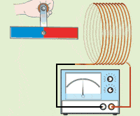
Can someone please provide graphical representation (waveform) of emf induced in coil due to a bar magnet spinning perpendicular to axis of coil.
magnetcoilrota.gif


Thanks,
SB
 
Last edited:
Physics news on Phys.org
Baluncore said:
A sinewave.
Yes, but in my opinion the waveform progression would be an irregular sinewave as there would be 2 positive peaks followed by 2 negative peaks (eg. M -- W) due to alternate rotation of N & S poles of the spinning bar magnet. I just wanted to visualize the graphical representation of my assumption.
 
The voltage is proportional to the rate of change of the magnetic flux passing through the coil.
For a spinning bar magnet that will be a sinewave.
 
  • Like
Likes   Reactions: vanhees71
Paul Colby said:
If the bar axis is perpendicular to the coil axis, isn’t the amplitude ideally 0? The total flux through the coil area is constant?
The magnet spins perpendicular to axis of coil. So a sinewave will be induced in coil but it's pattern would alternate between double positive and negative peaks in progression as the N & S poles alternately sweep across the plane of the coil.

For eg., negative voltage peak as N pole approaches the plane of coil, then 0V at centre of coil when flux is maximum and again positive voltage peak as N pole leaves the plane of coil. Same pattern will repeat but with inverted voltage peaks when S pole sweeps along. I just wanted to confirm whether my assumption was correct.
 
Last edited:
  • Like
Likes   Reactions: rude man
b.shahvir said:
The magnet spins perpendicular to axis of coil.
This doesn’t define the geometry. The magnet’s axis of rotation is defined as perpendicular to the coil axis. What is the angle between the magnets rotation axis and the magnets magnetic moment? If this unspecified angle is zero, the amplitude will likewise be zero.
 
The bar magnet rotates about it's axis which lies in a plane perpendicular to axis of the coil such that an emf will be induced in the coil. As i mentioned above the N & S poles will be sweep across the face of the coil.
 
A picture worth a thousands words and I think in this case even more. If you can post a picture where you show the coil and the bar magnet and how exactly the bar magnet rotates.
 
  • Like
Likes   Reactions: vanhees71
Delta2 said:
A picture worth a thousands words and I think in this case even more. If you can post a picture where you show the coil and the bar magnet and how exactly the bar magnet rotates.
magnetcoilrota.gif


The magnet is rotated about it's axis as illustrated in figure above. The axis of the magnet is perpendicular to the axis of the coil.
 
  • Like
Likes   Reactions: vanhees71 and Delta2
There is no simple expression for the magnetic flux that emerges from a bar magnet. The lines of flux exit the north pole and enter the south pole. I don't think there is a simple answer to what you are asking.
 
  • Like
Likes   Reactions: nasu, rude man and Delta2
It's classic case of electromagnetic induction but never found any graphical representation of same, hence the query.
 
Charles Link said:
The problem is too complicated for it to be one that is a standard textbook example. It may look simple enough, but another one in that category is the force between two bar magnets.
Actually this is common depiction in textbook physics but with output to galvanometer and not oscilloscope. I doubt if such arrangement is actually feasible in practical generators to generate proper sinewaves.
 
b.shahvir said:
So a sinewave will be induced in coil but it's pattern would alternate between double positive and negative peaks in progression as the N & S poles alternately sweep across the plane of the coil.
The voltage is not generated when the flux cuts one side and then the other side of the cylindrical coil. The voltage is generated by the changing flux through the area surrounded by the circular coil.
 
Charles Link said:
There is no simple expression for the magnetic flux that emerges from a bar magnet. The lines of flux exit the north pole and enter the south pole. I don't think there is a simple answer to what you are asking.
If we do the simplifying assumption that the magnetic field near the bar magnet is very similar to a homogeneous magnetic field then we can say that the resulting voltage will be a sine wave. But I don't know this assumption how close is to reality.
 
  • Like
Likes   Reactions: DaveE
Delta2 said:
If we do the simplifying assumption that the magnetic field near the bar magnet is very similar to a homogeneous magnetic field then we can say that the resulting voltage will be a sine wave. But I don't know this assumption how close is to reality.
I never mentioned flux cutting. But this arrangement will obey faraday's laws of EM such that voltage peak polarities will change each time the flux linking the coil changes due to instantaneous position of N and S poles with time.
I was anticipating waveform patterns to support by assumptions.
 
Delta2 said:
If we do the simplifying assumption that the magnetic field near the bar magnet is very similar to a homogeneous magnetic field then we can say that the resulting voltage will be a sine wave. But I don't know this assumption how close is to reality.
It would be a sine wave but with repeated double positive and negative peaks for N and S poles linkage respectively. I did not find any waveforms depicting this phenomenon exactly.
 
I don't follow the double positive and double negative features. The pole when it is farther away from the coil will have a much lesser effect. To quantify this is somewhat difficult, but it is not a sine wave at twice the frequency.
 
  • Like
Likes   Reactions: Delta2
Charles Link said:
I don't follow the double positive and double negative features. The pole when it is farther away from the coil will have a much lesser effect. To quantify this is somewhat difficult, but it is not a sine wave at twice the frequency.
Frequency depends on speed of spinning magnet so it would remain constant. But i presume the nature of sine wave patterns will differ in time.
 
If the bar magnet dipole was short relative to it's distance from the coil, then the voltage generated would closely approximate a sinewave. If the bar magnet was to remain fixed some distance away, while the coil was rotated in the field, then the coil voltage would be a sinewave.

I do not understand the alleged mechanism that might generate a polarity symmetric double hump, which in essence would constitute only odd harmonic distortion.
The sum of two sinewaves, (one generated by each end of the dipole), would also be a single hump sinewave.
 
Baluncore said:
The sum of two sinewaves, (one generated by each end of the dipole), would also be a single hump sinewave.
It cannot be a single hump sinewave due to 0 flux positions (between alternate N and S pole linkages) at regular intervals during rotation of magnet.
 
The zero flux occurs when the two poles effectively cancel. The zero flux positions are usually the points at which the flux is changing at the greatest rate. They are therefore the voltage peaks.
 
  • Like
Likes   Reactions: Charles Link
Baluncore said:
The zero flux occurs when the two poles effectively cancel. The zero flux positions are usually the points at which the flux is changing at the greatest rate. They are therefore the voltage peaks.
As per the swinging magnet experiment in the attached pdf, the voltage peak occurs when the magnet pole is just near the midpoint of the coil (for both cases of pole approaching and leaving the coil) as the rate of change of flux is maximum at that point. In my opinion this may be closest simulation of my rotating magnet case.
 

Attachments

The field rotates with the rotating magnet. With the swinging magnet the field translates and there is no reversal of the field direction.
 
Baluncore said:
The field rotates with the rotating magnet. With the swinging magnet the field translates and there is no reversal of the field direction.
Exactly. That's why the double hump sinewave phenomenon as the peaks will repeat twice and invert as each pole sweeps across the coil in alternation.
 
You must define some parameters.
1. The length of the coil.
2. The diameter of the coil.
3. The length of the bar magnet.
4. The distance from the centre of the coil to the centre of the bar magnet.
This discussion is pointless without those parameters.
 
Baluncore said:
You must define some parameters.
1. The length of the coil.
2. The diameter of the coil.
3. The length of the bar magnet.
4. The distance from the centre of the coil to the centre of the bar magnet.
This discussion is pointless without those parameters.
1. 0.5cm
2. 1cm
3. 1cm
4. 1cm
 
Baluncore said:
The zero flux occurs when the two poles effectively cancel. The zero flux positions are usually the points at which the flux is changing at the greatest rate. They are therefore the voltage peaks.
In this geometry (small coil, long thin magnet):
The zero flux positions occur when the magnet axis is 90 deg from the coil axis (this happens twice per rotation).
The position of maximum flux change occurs approximately when the magnet pole engages the coil edge (this happens twice for each pole face = four times per rotation)
The position of extremal flux is when the axes align and this gives a zero crossing for the voltage (two crossings per rotation)
So there can be double humps between zero crossings as the OP indicates. The rest is as you indicate detail.
 
  • Informative
Likes   Reactions: Delta2