anhnha
- 179
- 1
Hi,
This is not a homework question. I need to calculate input impedance for a LNA and this is part of it.
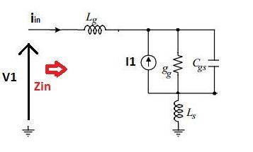
How do you calculate input impedance, Zin, for the circuit below?
I tried by applying an input voltage, V1, and calculate Iin.
Input impedance will be V1/Iin. However, the expression still contains V1 and I can't figure out how to
make it independent on V1.
There is another method that I am not sure.
Input impedance will be equal to the impedance as all independent sources are turned off.
This means that Zin in the picture will be equal to s(Lg + Ls) + 1/(gg + sCgs)
gg is a conductance.
This is not a homework question. I need to calculate input impedance for a LNA and this is part of it.
How do you calculate input impedance, Zin, for the circuit below?
I tried by applying an input voltage, V1, and calculate Iin.
Input impedance will be V1/Iin. However, the expression still contains V1 and I can't figure out how to
make it independent on V1.
There is another method that I am not sure.
Input impedance will be equal to the impedance as all independent sources are turned off.
This means that Zin in the picture will be equal to s(Lg + Ls) + 1/(gg + sCgs)
gg is a conductance.
Attachments
