Opposite Induced Currents in Circuit Explanation

Click For Summary
SUMMARY

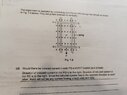
The discussion clarifies that in a circuit formed by rods and rails, the induced currents in segments PQ and RS flow in opposite directions, resulting in no net current. Specifically, the induced current in segment PQ is clockwise, while in segment RS it is anticlockwise. This phenomenon occurs because the electromotive force (emf) induced in each rod is aligned in the same direction, leading to cancellation of the emfs, akin to connecting two batteries in opposing orientations, which results in a total emf of zero in the circuit.

PREREQUISITES
  • Understanding of electromagnetic induction principles
  • Familiarity with circuit theory and current flow
  • Knowledge of electromotive force (emf) concepts
  • Basic grasp of the right-hand rule for current direction
NEXT STEPS
  • Study Faraday's Law of Electromagnetic Induction
  • Learn about Lenz's Law and its implications on current direction
  • Explore circuit analysis techniques for complex circuits
  • Investigate the effects of opposing emfs in electrical circuits
USEFUL FOR

Students of physics, electrical engineers, and anyone interested in understanding the principles of induced currents and circuit behavior in electromagnetic systems.

ellieee
Messages
78
Reaction score
6
Homework Statement
would there be induced current in rods PQ and RS?
Relevant Equations
nil
I don't understand why they said that the induced current flow is opposite to each other when it clearly states direction is to the right for both? https://www.physicsforums.com/attachments/285900
 

Attachments

  • 16261850189355184978004148639225.jpg
    16261850189355184978004148639225.jpg
    42.8 KB · Views: 132
Physics news on Phys.org
It's not quite clear (what is the experiment that is repeated?), but I think it means that if you consider the circuit formed by the rods and rails, the induced current in PQ is clockwise, and that in RS is anticlockwise, i.e. the opposite direction around the circuit, so there is no net current in the circuit.
 
  • Like
Likes   Reactions: rsk
Imagine a circuit where the current along the top line is L-R and the current along the bottom line is also L-R. It can't happen, because the current needs to flow around the circuit so must flow in the opposite direction in the top and bottom of the circuit.

So, in this case, the emf induced in each rod is in the same direction, so there can be no current because the emfs are cancelling each other out (like connecting two batteries facing each other) so the total emf in the circuit is zero.
 

Similar threads

Replies
4
Views
1K
  • · Replies 7 ·
Replies
7
Views
1K
  • · Replies 1 ·
Replies
1
Views
807
  • · Replies 2 ·
Replies
2
Views
2K
  • · Replies 16 ·
Replies
16
Views
1K
  • · Replies 1 ·
Replies
1
Views
2K
  • · Replies 3 ·
Replies
3
Views
3K
Replies
8
Views
2K
Replies
8
Views
1K
Replies
5
Views
1K