johnsmith7565
- 13
- 4
- Homework Statement
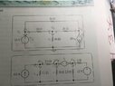
- Use the node voltage method to find v0 in the circuit shown.
- Relevant Equations
- (V0-v1)/R1 + (v1-v2)/R2+…= 0
What I’m stuck on is finding the constraint equation for i on the top question . I don’t know how to find it when it’s through a voltage source and not over any resistors. (I can’t use ohm‘s law) After I find i the problem should become easy to solve. I know that v1 = 10 and v2 = 20i . The KCL for v0 is (v0-10)/10 + v0/24 + (v0-20i)/20. I could write the KCL for v1 and v2 but that doesn’t address how to find the constraint which is what I need. And when I write them and solve for my answer is way off. Something tells me I need a new approach.
") .
.
 )
) ).
). but at least I can use it to see if the equations in the list are satisfied. Tomorrow (1 AM here
  )...
)... piece of cake !
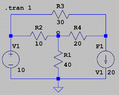
") counting and checking out eqns in #4
counting and checking out eqns in #4
 as well..
") ?
?