Engineering Help with my Karnaugh map circuit: it does not work

  • Thread starter Thread starter Noob of the Maths
  • Start date Start date
  • Tags Tags
    Circuit Map Work
AI Thread Summary
The user is experiencing issues with their Karnaugh map simplification, as the simulation does not match the truth table results. They express concern that their boolean equation appears overly complex, raising the possibility of errors in either the equation or the circuit itself. Respondents highlight the need for clearer communication, noting that the user's question lacks sufficient detail about the variables and their relationships. It is emphasized that boolean expressions can be large before simplification, and confusion arises from mismatched inputs and outputs in the circuit and truth table. Clarifying these details is crucial for effective troubleshooting.
Noob of the Maths
Messages
52
Reaction score
6
Homework Statement
Karnaugh map
Relevant Equations
ng
Hi! Good night ;)

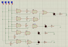
I have made the simplification of my circuit from the truth table using maps of.
Everything looks good, however the simulation does not work in many cases according to the truth table.

Captura de Pantalla 2022-03-10 a la(s) 0.47.06.png
Captura de Pantalla 2022-03-09 a la(s) 23.55.25.png

I notice that my boolean equation taken from the maps looks very big, is there the error?
Captura de Pantalla 2022-03-10 a la(s) 0.00.06.png

If it is ok, the error is my circuit?
tablaverdad.png


Thanks for read!
 

Attachments

  • Captura de Pantalla 2022-03-09 a la(s) 20.40.59.png
    Captura de Pantalla 2022-03-09 a la(s) 20.40.59.png
    139 KB · Views: 127
Physics news on Phys.org
One of the problems with social media sites like PF is that you are getting feedback from volunteers. They may choose to help or not depending on their own level of interest and the difficulty required. So, you will get more and/or better responses if you make your questions easy to understand.

I do know about K-maps and I am confident I could solve this problem. But, the way you've asked is frankly more confusing than the engineering required. I don't know what A, B, C, and D are or how they relate to the other table or the schematic (eg. what does D1 indicate). I suppose I could probably figure it out with reverse engineering, but I'm just not motivated enough right now given how confusing you've made it. When understanding the question is harder than solving the problem, I'll tend to move on.

So, maybe you could add some more detail about what you are doing and why? Maybe you could define some of the labels you've introduced?

Finally, boolean expressions that are derived from truth tables can be very big before they are reduced with logic. For example: ## xyz + xy\bar{z} + x\bar{y}z + x\bar{y}\bar{z} = x ##
 
Agreed.

For example, the circuit looks like ABCD are the inputs, but your truth table has different inputs and some inputs at the outputs?

1646926012924.png
 
berkeman said:
Agreed.

For example, the circuit looks like ABCD are the inputs, but your truth table has different inputs and some inputs at the outputs?

View attachment 298211
Yes, that's because the names corresponding to thins like "valve" "high level" "temperature" etc. but yes, it is ABCD
 
Noob of the Maths said:
Yes, that's because the names corresponding to thins like "valve" "high level" "temperature" etc. but yes, it is ABCD
Then what are the outputs?
 
Back
Top