Special One
- 32
- 1
- Homework Statement
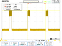
- f = 64.3 [Hz]
w = 1930 [RPM]
- Relevant Equations
- w=2*pi*f
Question: Why does the oscilloscope double almost the exact value of rotational speed measured by Tachometer?
Rotational speed from Tachometer = 1930 [RPM]
Frequency of 1 period = 64.3 [Hz] which means 3857.91 [RPM]
The output waveform of hall-effect sensor is attached.
Can you have any explanation please?
Rotational speed from Tachometer = 1930 [RPM]
Frequency of 1 period = 64.3 [Hz] which means 3857.91 [RPM]
The output waveform of hall-effect sensor is attached.
Can you have any explanation please?