Polplan in STATICS (instantaneous center of rotation?)

AI Thread Summary
The discussion revolves around the application of the instantaneous center of rotation (ICR) and the rules for determining hauptpol (ICR) and nebenpol in a movable system represented in a Polplan. Participants express confusion regarding the placement of the ICR for members II and III, particularly when considering the constraints of the system and the requirement for certain points to lie on a straight line. The conversation highlights the complexity of analyzing the movements of the links, especially when they are simultaneously rotating and translating. Additionally, there is mention of differing conventions in engineering education, particularly between German and other systems. The participants seek clarification on the rules and their application to better understand the mechanics involved.
arestes
Messages
84
Reaction score
4
TL;DR Summary
I need to find the ICR (hauptpol in german) in certain configurations.
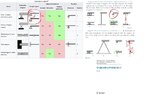
Hello. I understand that plotting the hauptpole (I believe it's called "instantaneous center of rotation" in English) in STATICS is useful for virtual displacements.
I know the rules: Hauptpol (ICR, which is denoted (0, #member) ) are located where a support of a member is fixed. For a member with a perpendicular support (only 1 force) it is along the perpendicular line, etc.

However, even though this image (see figure, "totpunkt") is obviously a movable system, I can't reconcile the rules. It appears as if member III has not hauptpole when obviously it's at infinity (since the member III can only displace vertically, no rotation). But one of the rules needs that the Nebenpole (the articulation joining III and II (2,3) and the other articulation joining I and II (1,2)) should lie on a straight line. This means that the ICR of III should be where I marked it... which is a contradiction.

What am I missing?
Also, how do I find hauptpol (ICR) for member II ? it only has articulation for which I have no rule to try and determine (0,2)

hauptpole.jpg
 
Last edited by a moderator:
Engineering news on Phys.org
arestes said:
However, even though this image (see figure, "totpunkt") is obviously a movable system, ...
Sorry, I fail to see a movable mechanism as represented.
Could you explain the possible movements of each link a little further, please?
 
Lnewqban said:
Sorry, I fail to see a movable mechanism as represented.
Could you explain the possible movements of each link a little further, please?
Sure, I am attaching two images (the one on the left is the one I was talking about). I drew the infinitesimal movements as a displacement du and angular displacements dphi1 dphi2. I guess it's right but only intuitively... but what I'm trying to figure out is the answers using Inst. Cent. of Rotat. (Hauptpol) by drawing a "Polplan". And for that, I'm having trouble applying the rules to find the Hauptpole (ICR) and Nebenpole.
hauptpole sans.jpg
 
Last edited by a moderator:
You may find some good ideas here:
https://www.real-world-physics-problems.com/instant-center.html

https://en.m.wikipedia.org/wiki/Instant_centre_of_rotation

Link II is simultaneously rotating and translating.
The top node follows a vertical line.
The bottom node follows a circular trajectory.
The geometrical center of link II must follow a trajectory that is a mix of both; therefore, its instantaneous center of zero velocity constantly changes positions during the movement of any slider-crank mechanism.


mechanism01b.gif
 
arestes said:
I am attaching two images
Sorry, I'm no mechanical expert, but aren't the diagonal hashed lines supposed to represent a fixed wall or other anchor? How can they move vertically? Did you meant to instead draw some sort of a vertical slip joint?

1738082386187.png
 
berkeman said:
Sorry, I'm no mechanical expert, but aren't the diagonal hashed lines supposed to represent a fixed wall or other anchor? How can they move vertically? Did you meant to instead draw some sort of a vertical slip joint?

View attachment 356490
Hi, I'm attaching the convention for figures used in my course and I believe it's common in many countries for Engineering: They only have one perpendicular reaction, allowing displacement parallel to the wall

Untitled.jpg
 
Lnewqban said:
You may find some good ideas here:
https://www.real-world-physics-problems.com/instant-center.html

https://en.m.wikipedia.org/wiki/Instant_centre_of_rotation

Link II is simultaneously rotating and translating.
The top node follows a vertical line.
The bottom node follows a circular trajectory.
The geometrical center of link II must follow a trajectory that is a mix of both; therefore, its instantaneous center of zero velocity constantly changes positions during the movement of any slider-crank mechanism.


View attachment 356488
Hi! First, thanks for the links and animation (may I ask where you found the animated gif? They might come in handy for me).
Also, unfortunately, I still can't for the life of me find the ICR for member II and member III. I am supposed to follow the rules to find them but I get a contradiction: On one hand I'm supposed to intersect to parallel lines perpendicular to the normal supports on the wall, forcing the ICR (Hauptpol) of II to be at infinity. That makes sense. But also, there's this rule that says that a Nebenpol and the Hauptpol should lie on a single line (possible counting infinity points of lines): (0,1) - (1,2) [Nebenpol, connecting I and II] - (2,0) but (0,1) - (1,2) is definitely not a line parallel to the previous ones.
Also, no idea as to how to find the Hauptpol (ICR) for member II. Still stuck.
Note: I understand these "rules" for Hauptpol and Nebenpol are a bit "niche" (I've only seen it in german schools and they're not explained in Statics book of the likes of Hibbeler). Here's a video explaining those rules, to get a sense of what I want to be able to do:
 
The velocity of the end attached to the shorter arm is perpendicular to the short arm. The velocity of the slide is always vertical. The lines for the IC come off perpendicular to the velocities of each endpoint.

1738115366163.png
 
arestes said:
Hi, I'm attaching the convention for figures used in my course and I believe it's common in many countries for Engineering:
Maybe you should discuss this convention with your professor or Teaching Assistant...

1738115835450.png


https://www.dtytutoring.com/EngineeringStatics.html
 
  • #10
berkeman said:
Maybe you should discuss this convention with your professor or Teaching Assistant...

View attachment 356519

https://www.dtytutoring.com/EngineeringStatics.html
haha, yeah, I'm aware of the different conventions for the figures, but it seems to be something of a regional fashion. The notation I gave is found almost everywhere in german universities, probably all across Europe, idk. It's on Wikipedia and books on Statics by german authors, such as Dietmar Gross, even translated into English by Springer. But anyway, it's not what I was asking for... :(
 

Attachments

  • Untitled.jpg
    Untitled.jpg
    35.4 KB · Views: 33
  • #11
erobz said:
The velocity of the end attached to the shorter arm is perpendicular to the short arm. The velocity of the slide is always vertical. The lines for the IC come off perpendicular to the velocities of each endpoint.

View attachment 356518
Hi! thanks. I was thinking of something like that but what I need is the IC when the whole mechanism is vertical. By analyzing it as a limit case I believe the IC of the middle member would be exactly at the joint at the upper end of it. But I can't make sense of it since it would have zero radius. Also, I was supposed to do this following the Hauptpole and Nebenpol rules, but at least I would like to know what's going on at that position.

It certaily baffles me that the upper end of the middle member would have zero radius
 
  • #12
arestes said:
Hi! First, thanks for the links and animation (may I ask where you found the animated gif? They might come in handy for me).
https://www.purdue.edu/freeform/me274/course-material/animations/

arestes said:
Also, unfortunately, I still can't for the life of me find the ICR for member II and member III.
Exactly when the three links are aligned, as shown in the original post, the IC of member II must be located at the top node.

The radius of rotation of link III is always infinite.
The radius of rotation of link II varies with time, but its value is 3/2l at top dead center (TDC).
The radius of rotation of link I is always l/2.

That position is normally called "top dead center" in slider-crank mechanisms because there is no vertical movement of the top link III or top node when the tangential instantaneous velocity of the lower node is perpendicular to that potentially sliding vertical movement (lowest link I or crank is in alignment with link II).

Please, see:
https://en.wikipedia.org/wiki/Slider-crank_linkage


AnimationAndModelingOfAutomotivePistonExample_08.gif
 

Similar threads

Back
Top