How Do You Calculate Static Pressure Drop in a Laminar Flow Channel?

AI Thread Summary
To calculate the static pressure drop in a laminar flow channel, one must consider the flow as steady state, incompressible, and fully developed. The channel geometry and fluid properties are essential, with the inlet velocity already determined. The solution involves using the Navier-Stokes equations, which may require numerical methods for complex geometries. For a simplified case, the pressure drop can be estimated using the Darcy friction factor and the Moody diagram, particularly for flow between parallel plates. Understanding these principles is crucial for accurately determining the pressure drop across the channel.
Darcy30
Messages
1
Reaction score
1
Hallo. Since I'm new in this field, I hope someone can help me.
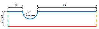
I have a laminar, steady state, incompressible flow in a channel (a fully developed).
Geometry of the channel is on the photo.
How should I calculate the drop of static pressure across the channel?
Since I have Re, I did calculate a inlet velocity, but now I'm stuck.
Thanks
 

Attachments

  • channel.png
    channel.png
    2.7 KB · Views: 233
Engineering news on Phys.org
To do this, you need to solve the Naiver Stokes equations, probably numerically. To get a lower bound to the pressure drop, you can at least solve analytically for the case where you remove the constriction and have rectilinear flow between parallel plates.
 
Hi Darcy30,

Was it intentional that your username would hint at the solution?

I understand the problem as follows:
  • Assume laminar, steady state, constant density (incompressible), fully developed flow.
  • Channel Geometry and Fluid Properties are known (I will assume the channel is circular)
  • The inlet velocity is known
Goal:
  • Find the pressure drop across a channel.
Solution Hint:
Darcy Friction Factor, Moody Diagram

Solution:

The pressure drop down a pipe is related to the friction factor.
For Laminar flow,
$$ f_D = \frac{64}{Re} $$
If not, then you will need to assume smooth walls or know the surface roughness.

The pressure drop is related to the following.
$$ dP = f_D * \frac{\rho*V^2*L}{2*D} $$
Break the problem into 3 sections. Inlet straight pipe, the circular restriction, and the outlet straight pipe. The inlet and outlet is straight forward. You will add up the dP for each section to find your answer.

The tricky part of this problem is that you need to integrate the friction factor (hence pressure drop) over the circular restriction. You need a formula for the relationship of Pipe Diameter, D, to length across the channel, x. Something like this:
$$ Dtube = 2 * R - R*sin(acos(R/x)) $$
Additionally, the velocity changes based on cross-sectional area. Use the conservation of mass to find that
$$ mdot = \rho*Area*Velocity $$
There is symmetry, so we only need to consider a 1/4 circle and multiply the friction factor by 2. Integrate from x = 0 to R. Or solve it numerically in a spreadsheet program with small steps of x.

PS: If the channel is indeed non-circular, then use the hydraulic diameter Dh in place of D.
$$ Dh = \frac {4*Area}{Perimeter} $$


References:
[1] Moody Diagram https://en.wikipedia.org/wiki/Moody_chart?msclkid=7b62d23aaee911ec823e165de974644a
[2] Hydraulic Diameter https://en.wikipedia.org/wiki/Hydraulic_diameter?msclkid=0899a52baef711ec890e442c37cca7b6
 
What is the exact statement of the problem?
 
How did you find PF?: Via Google search Hi, I have a vessel I 3D printed to investigate single bubble rise. The vessel has a 4 mm gap separated by acrylic panels. This is essentially my viewing chamber where I can record the bubble motion. The vessel is open to atmosphere. The bubble generation mechanism is composed of a syringe pump and glass capillary tube (Internal Diameter of 0.45 mm). I connect a 1/4” air line hose from the syringe to the capillary The bubble is formed at the tip...
Thread 'Physics of Stretch: What pressure does a band apply on a cylinder?'
Scenario 1 (figure 1) A continuous loop of elastic material is stretched around two metal bars. The top bar is attached to a load cell that reads force. The lower bar can be moved downwards to stretch the elastic material. The lower bar is moved downwards until the two bars are 1190mm apart, stretching the elastic material. The bars are 5mm thick, so the total internal loop length is 1200mm (1190mm + 5mm + 5mm). At this level of stretch, the load cell reads 45N tensile force. Key numbers...
I'd like to create a thread with links to 3-D Printer resources, including printers and software package suggestions. My motivations are selfish, as I have a 3-D printed project that I'm working on, and I'd like to buy a simple printer and use low cost software to make the first prototype. There are some previous threads about 3-D printing like this: https://www.physicsforums.com/threads/are-3d-printers-easy-to-use-yet.917489/ but none that address the overall topic (unless I've missed...
Back
Top