- 2,463
- 447
opps
Last edited:
Ranger Mike said:Who in their right mind would run a 40 gallon fuel cell on a short track 1/3 mile 20 lap race? Nascar has 17.5 gallon fuel cell limit for DAYTONA! Most local race tracks have 22 gallon maximum limit on fuel cells.
Most Saturday night warriors will run a 8 gallon to 15 gallon fuel cell depending on if they run an occasional ½ mile track. A 20 gallon cell is too big and a waste of space.
Where you going to mount this 40 gallon monster? Where you going to race it?
this is quite similar to the setup i run in my 04 port city, exception by track rules the front springs have to be a minimum of 325 to get a hundred pound weight break.Ranger Mike said:3/8 mile paved track late model BBSS setup
This email was sent to me and driver wants to have it posted to help other racers. I am keeping his name and address private but thank him for permitting the sharing of this project. We will be going thru the set up process changing from a ½ mile track package to a 3/8 mile setup. Driver walked the 3/8 track and majority of cars there are BBSS so the track is not that bumpy to take air off the car. Note - you do not need the latest greatest new chassis to be super competitive.
Note this is a Big Bar Soft Spring setup.
He says -
I have a ~2005 Port City straight rail asphalt
Late Model. It is a BBSS chassis.
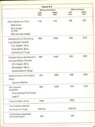
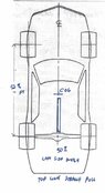
Here is how the car was setup to run a ½ mile asphalt track with sweeping flat turns. The car turned its fastest lap ever with this setup and was on rails. The car was scaled after the race (topped off fuel). Here are those numbers;TOTAL WEIGHT = 2702 lbs.
% Left = 57.8
% Rear = 49.8
% Diagonal = 55.2
*Swaybar Unhooked
RIDE HEIGHTS
LF = 4" RF = 4" RR = 4-1/2" LR= Floats
CORNER WEIGHTS, SPRING RATES, ETC.
LF = 713 lbs (26.4%) 180 lb spring. Camber +5½°
Caster +2°
RF = 642 lbs (23.8%) 185 lb spring. Camber -1½°
Caster +4°
LR = 850 lbs (31.5%) 225 lb spring.
RR = 497 lbs (18.4%) 400 lb spring.
SWAY BAR
1⅜" splined w/ 13" arms. Calculated @ ~532 lb.
SHOCKS
LF = S7Z RUSH7 16-2 COB
RF = 33-253015 RUSH DIRT LATE MODEL 12-2
LR = F4-B46-0210-HO RUSH7 6-1.5
RR = F4-B46-0210-HO RUSH7 4-3
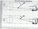
************Going forward, I will be racing this car on a ⅜ mile asphalt track. The whole track has 12° banking. The radius of both turns is ~161', which would be a diameter of ~322'.
Would you be able to put together a baseline setup package for this track?
Ie. Spring rates that will work with my 1⅜" sway bar (which I calc'ed at a rate of ~ 532 lbs), camber, caster, etc.
3/8 mile track rules - American Racer tires AR153 10 inch slicks
-Total weight will be Increasing to 2800 lbs. in 2022
- NO bump stops.
- 4" ride height.
- 58% max left side weight.***CURRENT CHASSIS CONFIGURATION***
NOV 27, 2021
Take note these numbers are with INCORRECT TIRE STAGGER. These numbers are with;
Front Stagger = 2¾"
Rear Stagger = 2½"
This was the only combination I had available.
One of the top teams suggested I run;
1½" FRONT STAGGER.
3" REAR STAGGER.
I previously did the math and 3" rear
stagger is about right.
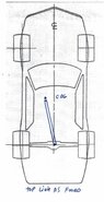
TOTAL WEIGHT "RACE READY" = 2747 lbs.
Left = 57.0% (1567 lbs)
Rear = 49.3% (1357 lbs)
Diagonal = 54.2%* (1491 lbs)
*Swaybar Preloaded one (1) turn
LR BITE +311 lbs
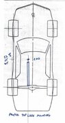
FRAME RIDE HEIGHTS:
LF = 4" RF = 4"
LR= ~4" (floats) RR = 4-1/2"
CORNER WEIGHTS, SPRING RATES, ETC.
LF = 733 lbs (26.7%) 180 lb spring. Camber +5½°
Caster +2°
RF = 657 lbs (23.9%) 185 lb spring. Camber -3°
Caster +4°
LR = 834 lbs (30.4%) 225 spring rate
RR = 523 lbs (19.0%) 400 spring rate
SWAY BAR
1⅜" DIAMETER, SPLINED.
3 PIECE W/13" ARMS.
CALCULATED @ ~532 LBS.
SHOCKS (BILSTEIN)
LF = S7Z RUSH7 16-2 COB
RF = 33-253015 RUSH DIRT LM 12-2
LR = F4-B46-0210-HO RUSH7 6-1.5
RR = F4-B46-0210-HO RUSH7 4-3
TIRE PRESSURES COLD
LF = 12 psi
RF = 18 psi
LR = 10 - 12 psi
RR = 18 psiInitially, my final rear gear ratio will be 6.02.
I do expect that to change.
A 6600 RPM rev limiting chip is currently installed. Could go to 7000 RPM in the future. Any more would be pushing past what the camshaft has to offer. No sense in beating a dead horse!