- 2,463
- 447
thanks for the input..always good to get this from other racers! HAppy Easter!

Indeed. But it's still a modification that would need to be done.Ranger Mike said:All you need to make engines reverse rotating is a reverse starter and camshaft and gear drive both commonly available in marine engines
Hi Ranger Mike,Ranger Mike said:We found out the top link mounting point on the rear end was same setting as from the Port City factory. We are running 58% left side weight so the distance from right rear tire centerline to tip link mount was off 6". since we can only use solid links , no springer top link or spring trailing arms, the mount location is vital to good tire hook up. As found distance from rt rear CL was 32" on 66" rear track width. So 58% left side weight means the mount point is 66 x .58 = 38.25" and changing it means both rear tires are loading the same.
Thanks RM for all the information you provide and the reference guide to various topics. Being new to this forum, this information helps me quickly find information and hopefully, will keep me from asking the same question twice...LOL. THanks Again!Ranger Mike said:3rd link mounting 253 8
3rd link mounting 707 21
3rd link mounting 81 3
3rd link mounting 1603 46
3rd link spring rate 261 17
4 link I C 301 16
4 link rear suspension 132 9
Ackermann 646 33
Aero Burnulli effect 574 29
Anti Dive 403 21
Anti Dive 492 25
Anti Squat 314 16
Anti Squat 327 17
ARB (sway bar) front 357 18
ARB (sway bar) front 358 18
ARB (sway bar) rear 521 27
Benchmark the car 285 15
Big Bar Soft Spring 1118 56
Big Bar Soft Spring 362 19
Big Bar Soft Spring 381 20
Big Bar Soft Spring 568 29
Bump steer 13 1
bump steer 643 36
bump stops 220 11
Camber build 663 37
Caster 319 16
Center of Gravity 563 29
Chevelle rear end 830 42
design suspension from scratch 388 12
design suspension from scratch 566 19
Eccentric 229 12
Front RC location 251 9
Front RC location 691 24
Fuel Cell location 272 14
Fuel Cell location 505 26
Gas shock tuning 217 11
Heat cycle machine 572 29
Hotchkiss suspension 353 18
jacking effect 229 13
jacking effect 691 35
jacking effect 811 41
jacking effect 879 44
Lead - front end geometry 1369 69
leaf spring 789 40
leaf spring 1322 67
Light is right 560 28
Metric clip street stock rear end 301 16
Metric clip street stock rear arb 521 27
Metric clip street stock 830 42
Metric clip street stock 832 42
Metric clip street stock rear steer 858 43
Metric clip street stock 1264 64
Metric Spindle swap 284 15
Metric Spindle swap 809 41
Motion rate - rear 308 16
Myth of Weight Transfer 228 12
Myth of Weight Transfer 676 34
Myth of Weight Transfer 811 41
Myth of Weight Transfer 676 34
Myth of Weight Transfer 228 12
Myth of Weight Transfer 676 38
Myth of Weight Transfer 470 24
Panhard bar 246 13
Penske shocks 217 11
Polar moment 562 29
progressive spring 216 11
Race Line 667 38
RC Height 229 12
rear end camber 1326 67
Rear end Instant Center 301 16
Rear roll steer video 1200 60
Rear roll steer video 858 43
rear steer 116 8
rear steer 81 5
Ride height 552 28
Roll center & offset 229 8
Roll center distribution 229 8
Scrub radius 325 17
Shocks (dampers) 703 40
Spindle Angle 325 17
Spindle Angle 332 17
spring rate calculations 19 2
spring rate calculations 589 30
Spring rate vs wheel rate 17 2
Squaring the car 270 14
Squaring the car 479 24
Stagger 36 3
Stagger calc 36 2
Stagger tape 426 27
Street Stock 1314 66
Street Stock 1264 64
Street Stock 830 42
Street Stock 832 42
Stringing the car 269 14
Stringing the car 293 15
Tire down force 62 4
Tire temp readings 468 24
Track width 255 13
Track width 264 14
Track width 322 17
Track width 505 26
Upper A-arm angle 312 16
Wheelbase 264 14
Ranger Mike said:Thank you Racerman,,exactly what I was talking about! 3rd link properly connected. Good job!
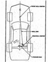
Why is top link mount so critical?
The top link is the rear end link that pulls the race car. This is why the spring type top links have a compression spring to lessen the rear end loading when you get back on the gas at corner exit. This top link directs all rear end force to the chassis. The rear tires grip the track and try to pull the rear end to the rear as the trailing arms on the bottom push the car to the front and try to climb up under the car.
Why location matters- In road course car set ups you want everything set up 50/50 % weight bias, so all front tires scale close to equal and the rear end tires scale equal.
Not so on left turn racers where you want a left side weight bias. When in a turn you want the left side weight rolling over to the right side to assist the car with better traction (tire grip).
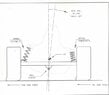
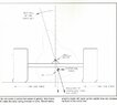
Imagine a you have a log chain and a 5 foot x 5 foot x 4 foot box. You want to pull a 2800 pound box and inside a spare engine located to the left side and a few old tires filling up the other side.
You want to find the center of mass so the box will slide straight and not pull to one side. If you use the centerline of the box and hook the chain at 2 ½ foot. The box will not slide straight as you pull it. You have not pulled the box on its Center of Mass. If the top link is offset to the right of the center of mass, the right rear tire will be loaded more and the left rear tire will be loaded less. We have a push or understeer situation just like when you have too soft a right rear spring. Right rear has too much traction. This is why you have a mystery induced push on corner exit. You are not loading the tires equally when you step on the gas coming out of the turn.
So you need to mount the top link as my post 81 on page 3, post 253 on page 8, post 707 page 21 show.
@Ranger Mike ,Ranger Mike said:RAceman
A level panhard bar ( same mounting height on both sides) means force is vectored laterally to the tires. Any angle up hill to the right rear will cause upward force on both tires and unload both tires. Now you have to compensate with spring change. A 1/2 inch height change from level can make significant handling changes.
Spot on !Ranger Mike said:If the Rules say it, you know what you can't do! But EVERYTHING ELSE is open..if you dont do it , some other racer will or already has it.