Resonant cavity and circuit analysis

Join the discussion
Registration is free. Ask a follow-up in this thread, or start your own.
4 replies · 2K views
dRic2
Gold Member
Messages
887
Reaction score
225
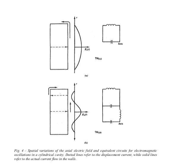
As I understand, if you solve the Maxwell's field equations for a resonant cavity, supposing a time dependence of the form ##e^{iwt}##, you get an eigenvalue problem and different modes as possible solutions. I'm reading some notes where the author states that each mode can be associated with a corresponding RCL circuit. Assuming ideal conducting walls you have no resistances (a part from a possible device to which the cavity is coupled), but I don't get how to draw the corresponding circuit for each TM or TE mode. To better explain myself I'll post some pictures:
Schermata 2020-05-06 alle 23.31.31.png
Schermata 2020-05-06 alle 23.31.35.png
 
Physics news on Phys.org
You should start with each extremum of E corresponding to capacitor, and node corresponding to inductor. You will get ladder circuit. Afterward, you need to treat each section of ladder as resonator in primary resonance, and calculate values of L and C. After calculation is complete for each section, produce the equivalent circuit for the frequency of interest. Some sections will reduce to single capacitors, while others - for single inductors.
For example, TM02 will have 11 elements (8 inductors and 3 capacitors) before reduction. Of course, such LC circuit approximation is intrinsically narrowband.
 
  • Like
Likes   Reactions: dRic2
Thanks a lot. But I am pretty weak in both E&M and circuit analysis...

trurle said:
You should start with each extremum of E corresponding to capacitor, and node corresponding to inductor.
Can you explain why this is so?
 
dRic2 said:
Can you explain why this is so?
Extremum of E corresponds to resonator area with large swings of voltage but low currents. This state is well approximated by capacitor. Opposite is correct for zero of electric field.
 
trurle said:
low currents
Why do you say that ? I suppose we are talking about induced currents, but I don't see it