Engineering Simulink: How to fix given error for a closed loop model w/ PID controller?

  • Thread starter Thread starter simphys
  • Start date Start date
  • Tags Tags
    Simulink
Click For Summary
To resolve the error in the closed-loop Simulink model with a PID controller, users are advised to check the values of all components and variables for accuracy, ensuring correct signs and units are used. It is suggested that a common issue may arise from incorrect notation, such as using 'm' instead of 'M'. Additionally, adjusting the time step or error band may help mitigate the problem as indicated by the error message. Users are encouraged to share updates on their troubleshooting progress. Proper validation of model parameters is crucial for effective simulation.
simphys
Messages
327
Reaction score
46
Homework Statement
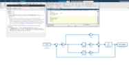
The question that is asked is basically to create a closed loop model with a PID controller. (if necessary more information on the picture)
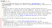
The problem that I am encountering is an error which I don't understand and know how to fix?
Relevant Equations
not relevant
Could I get some input on how to fix this problem please? Thanks in advance!

The exercise for which I need the model.
Screenshot from 2023-06-07 17-26-12.png
Screenshot from 2023-06-07 17-25-52.png


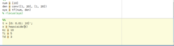
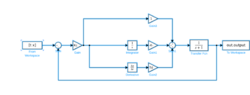
The simulink model together + the error that needs to be fixed + Matlab code used:


Note: Gain 1 = 1/Ti
 

Attachments

  • Screenshot from 2023-06-07 17-33-21.png
    Screenshot from 2023-06-07 17-33-21.png
    26.5 KB · Views: 136
  • error.png
    error.png
    22.5 KB · Views: 152
  • matlab_code.png
    matlab_code.png
    5.3 KB · Views: 126
  • simulink_model.png
    simulink_model.png
    7.4 KB · Views: 153
Physics news on Phys.org
I'm not an expert on this, but it looks like some of the equations it is solving are changing in value so fast that further calculations make no sense.

Please check the values of all the components/variables you have supplied. For instance maybe one is missing a minus sign or a decimal point. Another common problem is that an 'm' was entered instead of 'M' (or the other way around -- one means milli-, the other Mega-).

Then try changing the time step or error band, as the Error Msg. suggested.

Good Luck,
Tom

p.s. please keep us posted on what you find that works.
 
Thread 'Full bridge circuit with inductor and resistor'
The above is the circuit i am calculating the inductor current. During the positive half of the sine input D1 and D3 are conducting so the circuit becomes My calculations are as below Are the above equations ok? When transitioning from +Ve cycle to -Ve sine wave does the above equations still applicable? During the negative cycle the diodes D2 and D4 are conducting and the current direction is going into the inductor same as when diodes D1 and D3 are conducting. According to me the same...