Wireless Power Transfer (is this correct)

Join the discussion
Ask a follow-up here, or get your own question answered by working scientists, mathematicians and engineers — people, not an autocomplete.
Real named experts · corrections over time · the nuance an AI answer skips
5 replies · 2K views
jaus tail
Messages
613
Reaction score
48
TL;DR
Circuit Operation:
Ref: https://www.semanticscholar.org/paper/Design-and-Simulation-of-Different-Wireless-Power-Baroi-Isla m/dc19ecfde904964704777ab5adef96d5d6846f1f
1572628388867.png


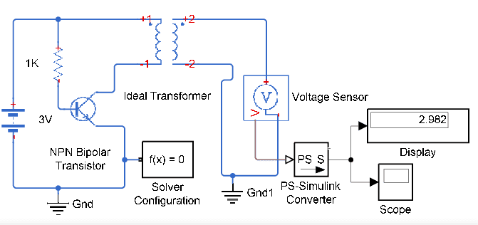
I couldn't find the working of this circuit so I guess it would be like:
Initially transistor is OFF, so the current flows through Base, and then when transistor is ON, the current flows through transistor Collector to Emitter, so now it flows down the transformer. Base current is reducing and then transistor turns off, so then flux falls. And then again current flows through Base, so cycle continues?

Is this correct? But if current flows through base initially, and if Emitter current is zero, so where does the base current come out from? Emitter current is Beta times collector current. Collector current is zero, so emitter current would also be zero, right?

 
Engineering news on Phys.org
Which figure is that from at the link? It looks wrong, and is missing some way to make the left hand side oscillate, IMO. Is it from Figure 5?

1572633818698.png
 
  • Like
Likes   Reactions: jaus tail
Oh, maybe you posted Figure 6. Still looks wrong to me, though...
 
  • Like
Likes   Reactions: jaus tail
But I drew the original circuit that I have posted in MATLAB simulink and was able to get oscillations. I had kept source voltage around 0.4V
 
How
berkeman said:
Which figure is that from at the link? It looks wrong, and is missing some way to make the left hand side oscillate, IMO. Is it from Figure 5?

View attachment 252164
Could you explain the working of this circuit?
I found a slightly difference circuit:
1572842917182.png

It says:
In transmitter section, the Transistor is generating high-frequency AC current across the coil and the coil is generating a magnetic field around it. As the coil is center tapped, the two sides of the coil start to charge up. One side of the coil is connected to the resistor and another side is connected to the collector terminal of NPN transistor. During the charging condition, the base resistor starts to conduct which eventually turns on the transistor. The transistor then discharges the inductor as the emitter is connected with the ground. This charging and discharging of the inductor produces a very high frequency oscillation signal which is further transmitted as a magnetic field.

Ref: https://circuitdigest.com/electronic-circuits/simple-wireless-power-transmission-circuit-diagram
 
In transmitter section, the Transistor is generating high-frequency AC current across the coil and the coil is generating a magnetic field around it. As the coil is center tapped, the two sides of the coil start to charge up. One side of the coil is connected to the resistor and another side is connected to the collector terminal of NPN transistor. During the charging condition, the base resistor starts to conduct which eventually turns on the transistor. The transistor then discharges the inductor as the emitter is connected with the ground. This charging and discharging of the inductor produces a very high frequency oscillation signal which is further transmitted as a magnetic field.

That explanation really makes no sense. "discharging an inductor" ?
What happens both of the 17-turns inductors are wound into a transformer. Once the transistor starts to conduct, the much large collector current will turn off the base current. Negative feedback + time delay + enough amplification will produce oscillation.
 
Last edited by a moderator:
  • Like
Likes   Reactions: jaus tail