AC supply - Signal generator - CRO in circuits

In summary: However, it is always best to check the specifications of the specific signal generator being used to confirm the type of measurement being displayed.
  • #1
PhysicStud01
174
0
Moved from a technical forum, so homework template missing
Hello,
This problem is about a.c. I am used to simply using basic a.c. supply symbol in circuit diagrams.

p5-j13q1.png

Here, I need to draw the set-up for an experiment where I can change the frequency of the supply (not the voltage) and see how this affect the peak current through a coil.

how can i change the frequency and how do I measure it. I have never drawn circuits like that. Will the signal generator be part of the circuit or is it simply connected to the a.c. alone?

also, how would I measure the current. Won't an ammeter's pointer keep on oscillating or will I have the rms value? or should I use a cro?

I do not have any apparatus to try this, nor can I find any explanation about this in books?
 

Attachments

  • p5-j13q1.png
    p5-j13q1.png
    15 KB · Views: 1,197
Physics news on Phys.org
  • #2
PhysicStud01 said:
how can i change the frequency and how do I measure it. I have never drawn circuits like that. Will the signal generator be part of the circuit or is it simply connected to the a.c. alone?

also, how would I measure the current. Won't an ammeter's pointer keep on oscillating or will I have the rms value? or should I use a cro?

Your questions are not about circuits, but the signal generator and the ammeter.

When you see the signal generator, there will be a knob or some other adjustment for frequency.

AC ammeters do not vibrate. There are many ways to measure DC and AC current. Read about them here https://en.wikipedia.org/wiki/Ammeter
 
  • #3
anorlunda said:
Your questions are not about circuits, but the signal generator and the ammeter.

When you see the signal generator, there will be a knob or some other adjustment for frequency.

AC ammeters do not vibrate. There are many ways to measure DC and AC current. Read about them here https://en.wikipedia.org/wiki/Ammeter
in a circuit diagram, how do I show this?
 
  • #4
There are no univeral symbols for those. You try a sketch and post it here with the UPLOAD button.
 
  • #5
should there be a signal generator connected to the ac supply or can we obtain the frequency directly from an a.c supply?
 
  • #7
anorlunda said:
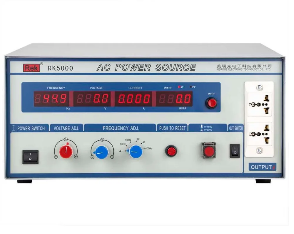
Here is a picture of a typical variable frequency source. It needs to be connected to a source. Some models use a DC source, some use an AC source. You could show a picture like this on the schematic rather than a symbol.

AC-Power-Source-RK5000-Variable-frequency-power-supply-Power-500W.jpg

I found the picture using this link
https://www.google.com/search?tbm=i...g...0..0j35i39j0i30j0i5i30j0i8i30.j8-jqMnYcbk
thanks. So, I can use this independently, without a signal generator or cro to find the frequency?
 

Attachments

  • AC-Power-Source-RK5000-Variable-frequency-power-supply-Power-500W.jpg
    AC-Power-Source-RK5000-Variable-frequency-power-supply-Power-500W.jpg
    41.8 KB · Views: 459
  • #8
PhysicStud01 said:
without a signal generator

It is a signal generator. You set the frequency with knobs.
 
  • #9
anorlunda said:
It is a signal generator. You set the frequency with knobs.
thanks. but are the values for V and I displayed on this generator rms values or peak values
 
  • #10
It is usually safe to assume that AC measurements are displayed as RMS values, unless stated otherwise.
 

1. What is an AC supply and how is it used in circuits?

An AC supply, or alternating current supply, is a type of electrical power that periodically reverses direction. It is used in circuits to power devices that require a changing voltage or current, such as electric motors. AC supplies are typically generated by power plants and delivered to homes and businesses through power lines.

2. What is a signal generator and why is it useful in circuit testing?

A signal generator is a device that produces electronic signals, such as sine waves, square waves, or pulses, at a specific frequency and amplitude. It is useful in circuit testing because it allows engineers and scientists to simulate different input signals and observe the response of the circuit. This helps in troubleshooting and designing new circuits.

3. What is a CRO and how is it used in circuits?

A CRO, or cathode ray oscilloscope, is a type of electronic test instrument that displays the waveform of an electrical signal. It is used in circuits to visualize and measure the voltage and current signals at different points in the circuit. This allows for precise analysis of circuit behavior and helps in diagnosing and fixing any issues.

4. How do I connect an AC supply, signal generator, and CRO in a circuit?

To connect an AC supply, signal generator, and CRO in a circuit, you will need to use appropriate cables and connectors. The AC supply should be connected to the power source, the signal generator to the input of the circuit, and the CRO to the output of the circuit. It is important to follow the instructions and safety precautions provided by the equipment manufacturers.

5. Are there any safety precautions I should take when using an AC supply, signal generator, and CRO in circuits?

Yes, there are several safety precautions that should be taken when using an AC supply, signal generator, and CRO in circuits. These include wearing appropriate personal protective equipment, carefully following instructions and safety guidelines, and ensuring that the equipment is properly grounded. It is also important to double check all connections and turn off the equipment before making any changes to the circuit.

Similar threads

  • Introductory Physics Homework Help
Replies
3
Views
2K
  • Introductory Physics Homework Help
Replies
2
Views
1K
  • Introductory Physics Homework Help
Replies
4
Views
1K
  • Electrical Engineering
Replies
13
Views
1K
  • Introductory Physics Homework Help
Replies
1
Views
1K
  • Introductory Physics Homework Help
Replies
6
Views
15K
  • Introductory Physics Homework Help
Replies
3
Views
1K
  • Introductory Physics Homework Help
Replies
2
Views
908
  • Introductory Physics Homework Help
Replies
4
Views
948
  • Electrical Engineering
Replies
2
Views
2K
Back
Top