Flyback Converter Magnetic Flux Calculation

Join the discussion
Registration is free. Ask a follow-up in this thread, or start your own.
4 replies · 3K views
BlackMelon
Messages
43
Reaction score
7
Hi

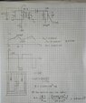
I am designing a flyback converter. The calculation (.jpg file) is based on Daniel W. Hart Power Electronics book. The transformer model consists only of an ideal transformer and its magnetizing inductance (or "primary inductance" in some textbooks).
The datasheet of the transformer's core is the pdf file "pq32_30". The other pdf file has details about the core's material (N87). So, I calculate the magnetic field density (B) at the narrowest area of the core. From this B value (217.032 mT) I do not expect to have any core saturation issue.

However, when I test the real circuit, I can see the peak of the MOSFET's drain current becoming exponential, which means the core saturates.

So, is there something wrong with my calculation?
 

Attachments
  • SaturationTrf.jpg
    SaturationTrf.jpg
    48.9 KB · Views: 219
  • N87 Saturation Data.pdf
    N87 Saturation Data.pdf
    402.3 KB · Views: 190
  • pq_32_30.pdf
    pq_32_30.pdf
    358.7 KB · Views: 174
Engineering news on Phys.org
Check the Drain current with the secondary open-circuit (no load, no filter cap). If the Drain current waveform is clean, your calculations did not include the load current.

edit: Or maybe the filter cap is shorted.
/edit;

Cheers,
Tom
 
Last edited:
Reply
  • Like
Likes   Reactions: BlackMelon
I don't understand how you can expect us to figure this out without knowing the core dimensions (Ac & lm).Also, I calculated a quite different value of Ipk in the primary, 0.673A (assuming 100% efficiency). Although we nearly agree on the current change in the primary ##\Delta I_p##.

Anyway, I'll leave you with my favorite magnetics design equations, which are often all you need for this sort of problem:

## B=\mu H = \mu \frac{NI}{l_m} ##
## L= \mu \frac{N^2 A_c}{l_m} ##

You can combine these to show that ##B=\frac{LI}{NA_c}##.

##A_c## is the effective core area.
##l_m## is the effective magnetic path length.

PS: Oops, I see the core is specified in your attachments. You'll get better (more) feedback if you really show your work better without making us look for it. Anyway with ##A_c =153.8 mm^2## I calculated ##B_{max} = 0.16T## which should be fine for ferrite. Of course it's actually a bit higher since your efficiency isn't 100%.
 
Last edited:
Reply
  • Like
Likes   Reactions: BlackMelon
How does the slope ##\frac{dI}{dt}## of the primary current compare to the expected value ##\frac{V_{in}}{L_m}## initially before the slope increases with saturation? This will tell you if the magnetizing inductance (i.e. air gap, turns, etc) is what you expected. How does the measured peak current compare to your calculations when you see saturation? Somewhere, your assumptions must be wrong.
 
Reply
  • Like
Likes   Reactions: BlackMelon
Hi All,
Actually, I figure it out why it saturates. The center of the transformer core (area named Ae) got the highest flux density, not its wing (even the wing's area is smaller than the center, it has much lesser flux). Please see my calculation on the mediafire link below. First, let me summarize/answers major concerns of each guy in here.
Tom: I include the load current. (actually, the increasing load current will increase the mean value of Lm)
DaveE: For B = LI/(NAc) I use "flux = LI/N" where flux is B*Ac. Same equation.
dI/dt and Vin/Lm is normal before saturation
See my calculation on the images.

https://www.mediafire.com/file/xsmzea322c2lull/Page1FB.jpg/file
https://www.mediafire.com/file/fzw9wnw0r0k57fj/Page2FB.jpg/file
I have attached some pages from Daniel Hart Power Electronics to show the proof of the formula I used. See the pdf file on attachment
 

Attachments

Last edited: