Discussion Overview
The discussion revolves around the geometry of magnetic field lines as they approach the poles of a magnet, particularly focusing on the shape and behavior of these lines in relation to an axially magnetized cylinder. Participants explore theoretical models, visual representations, and implications of magnetic field lines in various contexts.
Discussion Character
- Exploratory
- Technical explanation
- Conceptual clarification
- Debate/contested
- Mathematical reasoning
Main Points Raised
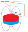
- Some participants propose that magnetic field lines are loops, with a potential "dead zone" at the center of the magnet where no lines are present.
- Others suggest that there may be a field line that runs through the center of the magnet, parallel to the axis, defining points of equal strength outward from the poles.
- There is a discussion about whether field lines represent points of equal magnitude, with some participants questioning this analogy to geographic contour lines.
- Some participants mention the importance of visualizing magnetic fields through simulations or experiments, such as using iron filings.
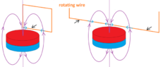
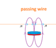
- There is a contention regarding the existence of a field line that does not curve back, with some arguing that it could lead to induced electromotive force (EMF) when a wire cuts through the magnetic field lines.
- Participants discuss the implications of field line density in relation to magnetic induction and the direction of induced voltages when cutting through the lines.
- Some express a desire for a three-dimensional gradient model of the magnetic field to better understand its shape and behavior.
Areas of Agreement / Disagreement
Participants do not reach a consensus on the exact nature of magnetic field lines, with multiple competing views on their geometry, behavior, and implications for electromagnetic induction remaining unresolved.
Contextual Notes
Participants reference various theoretical models and visual representations, but there are limitations in assumptions about the physical reality of field lines, which are acknowledged as mathematical abstractions. The discussion also highlights the complexity of visualizing magnetic fields and the potential for different interpretations based on context.