How to Calculate how much a column buckles?

  • Thread starter Thread starter Quietrabbit
  • Start date Start date
  • Tags Tags
    Buckling Column
AI Thread Summary
To calculate the compression of a column under applied force, a postbuckling analysis is necessary, as traditional methods like Euler's equation only address critical buckling forces. The end connections of the columns significantly affect the buckling behavior and final shape, requiring consideration of support conditions. For accurate results, utilizing finite element analysis software such as ANSYS or ABAQUS is recommended for nonlinear analysis. The behavior of a buckled column can be approximated as a constant force spring after initial buckling. Understanding these principles is crucial for effective design without relying on trial and error.
Quietrabbit
Messages
19
Reaction score
1
TL;DR Summary
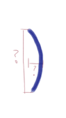
How to Calculate how much a column buckles. Ie horizontal measurement and new vertical length based on force applied.
I’m am looking for how to calculate the new horizontal and vertical “size” of a column based on the material and how much force is applied from the top/ends.
I have 3D printed TPU pillars that are made to compress and mold to a shape, but I am trying to figure out how much they will compress since that effects the shape I CAD. (I don’t want to trial and error the prints).
I have already looked into eulers equation but that seems to only give me the critical force which I know I am well past.
 

Attachments

  • A622540C-4995-4576-891A-88FDBD6FA84F.png
    A622540C-4995-4576-891A-88FDBD6FA84F.png
    6.1 KB · Views: 128
Engineering news on Phys.org
How are the end connections to the columns made?
That will determine the type of curve and the final chord length.
 
You will need to perform a postbuckling analysis which requires solving the large-deflection beam equation. An example of this can be found in Section 2.7 in "Theory of Elastic Stability" by Timoshenko and Gere. If their example does not match yours, you can try a search on postbuckling of beams.

If you have access to finite element analysis software with nonlinear analysis capability (e.g., ANSYS or ABAQUS), you could try doing your own analysis for your case.
 
The Euler equation predicts the force to buckle the column. That force, as alluded to by @Baluncore, is very dependent on the end support conditions. Your sketch shows simple supports, AKA pinned ends. Note that the Euler equation only applies to elastic buckling. Elastic buckling is when the column pops back to its starting shape after the load is removed.

After buckling, the force on an Euler column is roughly constant as the displacement increases. Two different search criteria that found good information are euler column constant force spring and post buckling euler columns. A good hit is this one: https://www.researchgate.net/figure...-spring-The-example-shown-here_fig1_349575713. One figure from that paper that shows this is:
Euler spring.jpg

That paper also has some references that look good.
 
How did you find PF?: Via Google search Hi, I have a vessel I 3D printed to investigate single bubble rise. The vessel has a 4 mm gap separated by acrylic panels. This is essentially my viewing chamber where I can record the bubble motion. The vessel is open to atmosphere. The bubble generation mechanism is composed of a syringe pump and glass capillary tube (Internal Diameter of 0.45 mm). I connect a 1/4” air line hose from the syringe to the capillary The bubble is formed at the tip...
Thread 'What type of toilet do I have?'
I was enrolled in an online plumbing course at Stratford University. My plumbing textbook lists four types of residential toilets: 1# upflush toilets 2# pressure assisted toilets 3# gravity-fed, rim jet toilets and 4# gravity-fed, siphon-jet toilets. I know my toilet is not an upflush toilet because my toilet is not below the sewage line, and my toilet does not have a grinder and a pump next to it to propel waste upwards. I am about 99% sure that my toilet is not a pressure assisted...
After over 25 years of engineering, designing and analyzing bolted joints, I just learned this little fact. According to ASME B1.2, Gages and Gaging for Unified Inch Screw Threads: "The no-go gage should not pass over more than three complete turns when inserted into the internal thread of the product. " 3 turns seems like way to much. I have some really critical nuts that are of standard geometry (5/8"-11 UNC 3B) and have about 4.5 threads when you account for the chamfers on either...

Similar threads

Back
Top