Maximizing Efficiency: The Role of Feedback in Boost Converter Switch Design

Join the discussion
Ask a follow-up here, or get your own question answered by working scientists, mathematicians and engineers — people, not an autocomplete.
Real named experts · corrections over time · the nuance an AI answer skips
7 replies · 4K views
TheRedDevil18
Messages
406
Reaction score
2
I'm looking into the design of the control circuit for the mosfet. If I know the output voltage and input voltage then I can find the duty cycle required. I found this schematic that uses feedback
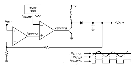
2031Fig07.gif

Source
https://www.maximintegrated.com/en/app-notes/index.mvp/id/2031

Why would I need feedback that changes the duty cycle like above ?, if the output voltage is dependent on the duty cycle and Vin and if those are fixed values then Vout should be constant regardless of load ?, also I'm a bit confused on the working of the above schematic, is it trying to maintain Verror of 0V regardless of changes in Vout ?
 
Engineering news on Phys.org
What makes you think that the Vin would be fixed? This is not often the case. There are other things that will cause the output voltage to droop when a load is applied also. You are thinking it backwards concerning the output voltage and the Verror. Verror does whatever it has to in order for the inverting and noninverting inputs of the opamp to remain virtually the same. This is a basic rule in opamp analysis. So if the reference is stable, can you see how the rest of the circuit will behave?
 
  • Like
Likes   Reactions: davenn
DC to DC converters behaves just like a ideal "DC" transformer. And for the boost converter n = Vout/Vin = 1/(1 - D) but this is true only when the inductor is working in continuous conduction mode (CCM), the inductor current never reaches 0A. And all component are ideal also Vin is kept constant.
And because we are living in non ideal world we need to change duty cycle to kept Vout at fixed value.
 
Averagesupernova said:
What makes you think that the Vin would be fixed? This is not often the case. There are other things that will cause the output voltage to droop when a load is applied also. You are thinking it backwards concerning the output voltage and the Verror. Verror does whatever it has to in order for the inverting and noninverting inputs of the opamp to remain virtually the same. This is a basic rule in opamp analysis. So if the reference is stable, can you see how the rest of the circuit will behave?

So basically Vref would be the max boost converter output voltage or voltage you are trying to maintain. So if for example we are trying to maintain 10V on the output and Vout drops to 9.7V then Verror is 10V-9.7V = 0.3V. If Verror increases then the duty cycle decreases. But if the voltage decreases then the duty cycle should increase since Vout = Vin/(1-D) ?
 
TheRedDevil18 said:
So basically Vref would be the max boost converter output voltage or voltage you are trying to maintain. So if for example we are trying to maintain 10V on the output and Vout drops to 9.7V then Verror is 10V-9.7V = 0.3V. If Verror increases then the duty cycle decreases. But if the voltage decreases then the duty cycle should increase since Vout = Vin/(1-D) ?
If Vout drops the voltage at Verror will rise, this means that as long as Verror > Vramp the voltage at Vswitch is high so the duty cycle increase.

170738_440698.jpg
 
Jony130 said:
If Vout drops the voltage at Verror will rise, this means that as long as Verror > Vramp the voltage at Vswitch is high so the duty cycle increase.

170738_440698.jpg

Ok, yes that makes sense. If I am designing a boost converter would I need a control system like this ?, What if I used a zener diode to fix the voltage regardless of current changes ?
 
TheRedDevil18 said:
What if I used a zener diode to fix the voltage regardless of current changes ?
It is wasteful of power, so you'd only use a zener to stabilize the output where the load draws low power. The attraction of a switching booster/regulator is that it can offer efficient operation at high power.