Discussion Overview
The discussion revolves around the challenges of measuring and converting a sinusoidal voltage from a capacitor in an induction heater circuit into a square wave without significantly altering the phase. Participants explore various methods for voltage reduction, including resistive and capacitive dividers, while addressing the impact of component choices on phase shift and signal integrity.
Discussion Character
- Technical explanation
- Debate/contested
- Experimental/applied
Main Points Raised
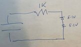
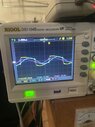
- One participant describes the need to reduce a 400Vrms sinusoidal voltage by a factor of 10 for use with a comparator, noting issues with phase shift when using resistive and capacitive dividers.
- Another participant suggests using series limiting resistors and diode clamps to manage the voltage seen by the comparators.
- Concerns are raised about the source impedance, cable capacitance, and load resistors affecting the measurement.
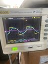
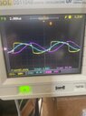
- Discussion includes how oscilloscopes manage to measure signals without affecting phase, with references to resistive and capacitive dividers used in their design.
- One participant proposes a high-pass filter approach to minimize phase shift and distortion.
- Another participant discusses the importance of impedance matching and the use of capacitive dividers for high AC voltages.
- Participants share their experiences with simulation software, mentioning tools like LTspice and Falstad for circuit analysis.
- One participant highlights the impact of tolerance errors in practical applications compared to theoretical models.
- Another participant points out the significance of self-heating in resistive dividers and the breakdown voltage ratings of components.
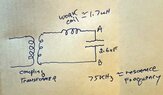
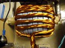
- A participant shares a schematic and details about their specific setup, expressing difficulties in measuring the tank capacitor voltage without affecting its phase.
- Suggestions include using specific capacitor values and configurations to achieve a desired voltage reduction without loading effects.
Areas of Agreement / Disagreement
Participants express various methods and ideas for voltage reduction and measurement, but there is no consensus on a single effective solution. Multiple competing views and approaches remain, with ongoing discussion about the implications of different component choices on phase and signal integrity.
Contextual Notes
Participants note limitations related to source impedance, stray inductances, and the effects of component tolerances on circuit performance. The discussion reflects a range of practical challenges in high-frequency signal measurement and manipulation.
Who May Find This Useful
Individuals working on high-frequency circuit design, particularly in applications involving induction heating, voltage measurement, and waveform shaping, may find this discussion relevant.