RC circuit solution to a current pulse input

Join the discussion
Ask a follow-up here, or get your own question answered by working scientists, mathematicians and engineers — people, not an autocomplete.
Real named experts · corrections over time · the nuance an AI answer skips
3 replies · 2K views
PhysicsTest
Messages
260
Reaction score
27
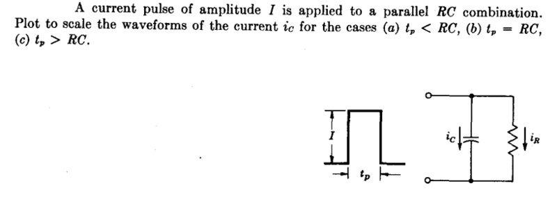
TL;DR Summary: A current pulse of amplitude I is applied to a parallel RC combination, plot to scale waveforms of the current ic for the cases a.tp < RC b. tp = RC c. tp > RC

1694245369471.png

1694253605899.png

1694253647973.png

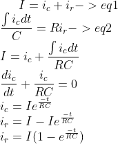
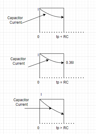
Are the calculations and waveforms correct?
 
Physics news on Phys.org
Your solution is correct. But your sketches all look nearly the same. I would draw it for ##t_p << RC##, ##t_p = RC##, and ##t_p >> RC##. I think that's the intent of this rather unclear question.
 
I'll also add a bit of hand waving intuition demonstrated by this problem. This is both an imprecise but really useful concept:

A resistor has the same impedance for all frequencies, but a capacitor has a decreasing impedance as the frequency increases. The parallel arrangement here creates a current divider, since the two devices share the same voltage.

So, if we look at the extreme cases:

1) Very short pulses (compared to ##\tau = RC##) are composed of high frequencies. This means that most of the current will flow through the capacitor because it will have a very low impedance and will not generate much voltage as that current passes through it, hence not much resistor current can flow. In the extreme case you can ignore the resistor.

2) Very long pulses (compared to ##\tau = RC##) contain low frequencies. This means that the current will charge the capacitor up to higher voltages (i.e. higher capacitor impedance) and will generate enough voltage so that the current flows mostly through the resistor. The current diverted away from the capacitor will limit its ability to continue to increase in voltage. In the extreme case you can ignore the capacitor for most all of the pulse.

3) Pulses roughly on the scale of ##\tau## will look like a mix of the two previous cases. Initially most of the current will flow through the capacitor. Later, most of the current will flow through the resistor. You can't ignore either component in this regime.

EEs make this sort of gross approximation often when analyzing real world circuits.
 
Last edited:
Reply
  • Like
Likes   Reactions: DeBangis21 and PhysicsTest
Another way to look at the circuit is via the exponential curves associated with the RC time constant.

Suppose you arbitrarily set the time constant to ##RC = 1~\rm{sec}## . Then you can adjust the value of ##t_p## accordingly. Arbitrarily set the current to 1 Ampere, too. All these values can be scaled accordingly, but this makes thing easier to work with.

When the source current goes from 0 to 1 amp, the capacitor current follows it as it look initially like a short circuit. Then the capacitor current will drop exponentially, right? The source current is fixed at 1 ampere but as the capacitor begins to charge it's current will drop and the corresponding (leftover current) goes to the resistor. The time constant of the circuit is ##RC##.

The next "event" happens when the source current drops again to zero. How much time occurs between the two events? That depends upon the value of ##t_p##, right? The pulse length depends upon ##t_p##. So how much the capacitor current drops from 1 depends upon ##t_p## and the time constant we've set arbitrarily to 1 second. If ##t_p## is greater than 6 or so ##RC##, then the capacitor current will drop to (effectively) zero during this time. If ##t_p## is less than ##RC## it will drop only fractionally.

Question: What happens to the capacitor current when the source current changes from 1 to 0?
 
Reply
  • Like
Likes   Reactions: PhysicsTest