Waveform of Classic Electromagnetic Induction

Click For Summary
The discussion centers on the waveform of electromotive force (emf) induced in a coil by a bar magnet spinning perpendicular to the coil's axis. Participants agree that the induced voltage will resemble a sine wave, but with alternating double positive and negative peaks due to the sequential passage of the magnet's north and south poles. The complexity of accurately depicting this phenomenon is acknowledged, as it does not conform to standard textbook examples, and the geometry of the setup significantly influences the waveform. The conversation highlights the importance of defining specific parameters, such as the dimensions of the coil and magnet, to better understand the induced emf. Ultimately, the waveform is characterized by zero flux positions and maximum flux changes occurring at specific points during the magnet's rotation.
  • #91
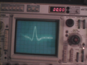
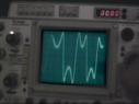
What you have here is a small electrical generator. One of the things I find most interesting is the cylindrical magnet and computing the magnetic field from it. See post 72. The calculation can be done by the magnetic pole method or by magnetic surface currents. Both methods get the identical result for the magnetic field.
 
  • Like
Likes b.shahvir
Physics news on Phys.org
  • #92
Well, I finally ran the experiment.

The hardest part was finding a bar magnet on short notice. Actually I never did find one locally, I did find a horseshoe magnet so I ran two experiments, one with the horseshoe and one with a bar (obtained by sacrificing the horseshoe).

The coil is a spool of 30 AWG wirewrap wire I had around (no idea how many turns, many) and the oscilloscope is a Tektronix 465.

The test with the U (horseshoe) magnet was done by hand-holding the magnet and sweeping it across the diameter of the coil

The string tied around the center of the bar magnet was used for suspension and twisted to supply spin to the magnet upon release. Magnet was approximately on the coil axis.

The funny 'scope traces are because they are a composite of video frames taken with a bargain-store pocket video camera that is many years old.

(There should be 4 images, preview shows 6. I'll try a post-and-edit for clean-up... Arrgh they changed from full size to thumbnails! Oh well.)

Cheers,
Tom
 

Attachments

  • SUNP0002.JPG
    SUNP0002.JPG
    14.9 KB · Views: 136
  • U-Composite.png
    U-Composite.png
    66.2 KB · Views: 129
  • SUNP0006.JPG
    SUNP0006.JPG
    18.4 KB · Views: 106
  • Bar-composite.png
    Bar-composite.png
    55.3 KB · Views: 146
Last edited:
  • Like
  • Love
Likes vanhees71, Charles Link, b.shahvir and 2 others
  • #93
Thank you very much for sharing the results of your experiment.

I think the result of Bar-composite.png seems similar to my previous prediction of induced voltage waveform.

My prediction is ## ~+A→-A→0→-A→+A##
But it is actually ##~+A~→0→-A→-A→0→+A##
1623309341788.png

.
 
  • Love
Likes Delta2
  • #94
Great work @Tom.G thanks for doing this experiment for all of us to confirm some of the theoretical discussion we had here.
 
  • Like
Likes vanhees71, Charles Link, b.shahvir and 1 other person
  • #95
Actually the prevailing opinion here is that we will have two positive humps and two negative humps with some zero inbetween

but

if I interpret the oscilloscope screens correct (I am not EE so I don't have experience of working with an oscilloscope) I think we have two positive humps (local maximums) with another positive reversed hump in between (local minimum) and two negative humps with another negative reversed hump in between.

We missed this extra reversed hump..
 
  • Like
Likes vanhees71 and b.shahvir
  • #96
Tom.G said:
Well, I finally ran the experiment.

Cheers,
Tom

Thanks very much for taking time out for science and helping us with the practical aspect of the discussion. I greatly appreciate your effort and am grateful for it.
The experimental results almost matches the theoretical assumptions related to this arrangement. However, the only contradiction to the assumption is the continuity of the double peaks. In my opinion it should have gone to 0 between the double peaks as below;
0 +A 0 -A 0 -A 0 +A 0 +A 0 -A 0 -A 0 +A and so on...
I wonder why there was no 0 state instead of continuous v curves in between the double peaks.
 
  • #97
Delta2 said:
Actually the prevailing opinion here is that we will have two positive humps and two negative humps with some zero inbetween

Exactly! because 0 state in between indicates periodic pole reversals when the magnet rotates. I presume it could be due to oscillations of the string during rotation (causing changing flux linkages) which may be preventing the voltages from dropping to 0 in between pole reversals, but am not sure.
 
  • #98
b.shahvir said:
Exactly! because 0 state in between indicates periodic pole reversals when the magnet rotates. I presume it could be due to oscillations of the string during rotation (causing changing flux linkages) which may be preventing the voltages from dropping to 0 in between pole reversals, but am not sure.
I think the voltage drops to 0 between pole reversals, but it does not drop to 0 in between the (positive) humps, instead it drops to a local minimum>0. (or local maximum <0 for the two negative humps).
 
  • #99
Delta2 said:
I think the voltage drops to 0 between pole reversals, but it does not drop to 0 in between the humps, instead it drops to a local minimum>0. (or local maximum <0).

In between the double peaks is the stage when the pole reversals take place. Voltage should go to 0 before each pole reversal.
 
  • #100
b.shahvir said:
In between the double peaks is the stage when the pole reversals take place. Voltage should go to 0 before each pole reversal.
Yes you are right that in between the double peaks is the pole reversal. But for some reason the voltage doesn't drop to 0, instead it goes to a local minimum.
 
  • Like
Likes b.shahvir
  • #101
Delta2 said:
Nope I don't agree with that, the two positive humps is when the north pole is approaching the coil and leaving the coil, and the third hump inbetween is when the north pole is aligned with the coil, that's what I think.
Similarly for the two negative humps and the south pole.

I would politely disagree. On careful analysis you will find the double humps(+ & - ) are actually formed when the poles reverse.

Let's say the the N pole is approaching the coil = 0 to +A
Next, the N pole is perfectly aligned with the axis of the coil = 0 state.
Again N pole is leaving the coil = 0 to -A
Next, the magnet is aligned perpendicular to axis of coil = 0 state
Next, the S pole is approaching the coil = 0 to -A (this is actually the 0 state between the double humps)
And the process continues as above...
 
  • Like
Likes hutchphd and Delta2
  • #102
b.shahvir said:
Next, the magnet is aligned perpendicular to axis of coil = 0 state
I disagree only with this, we don't get a 0 when this happens instead we get a positive local minimum (or a negative local maximum ).
 
  • Like
Likes hutchphd
  • #103
Delta2 said:
I disagree only with this, we don't get a 0 when this happens instead we get a positive local minimum (or a negative local maximum ).

Why? Could it be due to magnet field geometry or stray induction in oscilloscope probes or due to instability of the string! What prevents the voltage from going to 0 especially when the waveform is not a sinusoid.
 
  • #104
Is it an air coil or iron core coil? In my opinion the non zero state could be due to output current inductance in case of iron core coil.
Or maybe this is a current waveform. For proper voltage waveform you might require to drop it across a load resistance.
 
  • #105
b.shahvir said:
Is it an air coil or iron core coil? In my opinion the non zero state could be due to output current inductance in case of iron core coil.
Or maybe this is a current waveform. For proper voltage waveform you might require to drop it across a load resistance.
Could be due to the self inductance of the coil but I doubt it, i think its because of the magnet field geometry as you said.
 
  • Like
Likes alan123hk and b.shahvir
  • #106
It seems that we all have a consistent view of the waveform.

Actually my prediction is ##~+A→0-A→0→-A→+A→0→+A##
But the result of the experiment is ##~+A→0-A→\text{local max}→-A→+A→\text{local min}→+A##

I am also confused about why the zero that should appear between the double hump becomes a local minimum/maximum.

I agree that this may be caused by the geometry of the magnetic field, or more specifically, it may be because the relative positions and/or angles of the rotating magnet and the coil are not very symmetrical.
 
Last edited:
  • Like
Likes b.shahvir and Delta2
  • #107
The voltage is caused by the time derivative of the flux. When the poles are to the sides, and equidistant from the coil, the total flux is zero, but the derivative can be near maximum. This is where you observe the slight dip between the peaks, which occur just before and just after this position.
 
  • Like
Likes b.shahvir, vanhees71, alan123hk and 1 other person
  • #108
Charles Link said:
The voltage is caused by the time derivative of the flux. When the poles are to the sides, and equidistant from the coil, the total flux is zero, but the derivative can be near maximum. This is where you observe the slight dip between the peaks, which occur just before and just after this position.

I totally agree with your excellent analysis. When the magnetic poles are on both sides and are equidistant from the coil, the effective magnetic flux through the coil is zero, but this is only a point on the time axis. More importantly, even at this point in time, the magnetic flux through the coil is still changing, so now I believe this is the real cause.
 
  • Like
Likes Charles Link, b.shahvir and Delta2
  • #109
This simple home-made ac electrical generator would really make for a good experiment for undergraduate physics and EE students to perform. The mathematics could be refined by computing, per post 72, the magnetic flux from the cylindrical magnet. (It should be a fairly routine thing to computer program the magnetic flux, and numerically compute the time derivatives, etc., to compare experimental with theoretical). Thank you @Tom.G for supplying us with some very good experimental data in post 92. :)
 
  • Like
Likes Tom.G, b.shahvir and Delta2
  • #110
Charles Link said:
This simple home-made ac electrical generator would really make for a good experiment for undergraduate physics and EE students to perform. The mathematics could be refined by computing, per post 72, the magnetic flux from the cylindrical magnet. (It should be a fairly routine thing to computer program the magnetic flux, and numerically compute the time derivatives, etc., to compare experimental with theoretical). Thank you @Tom.G for supplying us with some very good experimental data in post 92. :)

As inferred from the experiment, we find that the output waveforms are quite unique and not a sinusoid. But sadly, theoretical representation (wherever I was able to observe) always indicate it as a sinusoid.
This gives an incorrect impression to the students that under all and any arrangement of faraday's EMI apparatus, the result will always be sinusoidal. Thanks to Tom, we can now clearly see the real picture. I once again am very grateful to Tom for this.
 
  • #111
b.shahvir said:
Is it an air coil or iron core coil?
Air.

Speculation here, could the dip between the double-humps be when the magnet axis is parallel to the coil axis?

It will be a few days before I have the opportunity to document the magnet position vs. waveform.

Cheers,
Tom
 
  • Like
Likes Charles Link, b.shahvir and Delta2
  • #112
Tom.G said:
Speculation here, could the dip between the double-humps be when the magnet axis is parallel to the coil axis?
See post 107. I believe it occurs when the two are perpendicular.
 
  • Like
Likes hutchphd, Delta2 and b.shahvir
  • #113
Can this experiment be redone with a longer bar magnet? I believe in this case the interim state between 2 double humps would then drop to 0.
 
  • #114
The idea of an iron core (post 104) is an interesting one. I do think in that case the iron in the core might reach a state of saturation during much of the cycle. If that indeed is the case, the voltage would see a spike, followed by a lengthy duration near zero, and then a spike in the reverse direction, followed by a lengthy duration near zero. It would be interesting to see if this is indeed the case. If the core didn't saturate, it could result in a stronger signal. One additional experiment would be to move the magnet farther away, and see if the iron core would then be free of saturation.
 
  • #115
b.shahvir said:
Can this experiment be redone with a longer bar magnet? I believe in this case the interim state between 2 double humps would then drop to 0.
If the induced voltage of the coil becomes zero between the double humps, it will take some time for the magnetic flux through the coil to remain constant. If this happens, one of the sufficient conditions should be that the rotating magnet must produce concentric magnetic lines of force within a certain angle range. But is it possible for a magnet to produce such magnetic field lines of force?

https://en.wikipedia.org/wiki/Magnetic_dipole#/media/File:VFPt_dipoles_magnetic.svg
 
Last edited:
  • #116
Actually it's the other way round. I believe the length of the magnet will directly influence the magnetic field geometry and hence the output voltage waveform. Consider the long bar magnet aligned perpendicular to axis of coil (vertical). In this case, the voltage dip will be significant (might even drop to 0) as the flux lines are more flattened at this position indicating a very slow rate of change of flux.
If it were a short dipole or a one turn air coil, then the induced voltage would have been maximum at above position. This is because the flux lines would be semicircular and the rate of change of flux linkage will be maximum at this position producing a perfectly sinusoidal output waveform. I hope my interpretation is correct.
 
  • #117
b.shahvir said:
producing a perfectly sinusoidal output waveform
I think in order to get a perfectly sinusoidal voltage we need a homogeneous magnetic field rotating (or a coil rotating inside a homogeneous magnetic field). The field from any sort of dipole is not homogeneous. It can be almost homogeneous very near the poles but varies greatly when you move far away from the poles.

The two humps look like they are part of a sinusoidal curve, but they are formed when the poles are approaching the coil, so that the field there is almost homogeneous.
 
  • #118
Delta2 said:
I think in order to get a perfectly sinusoidal voltage we need a homogeneous magnetic field rotating (or a coil rotating inside a homogeneous magnetic field). The field from any sort of dipole is not homogeneous. It can be almost homogeneous very near the poles but varies greatly when you move far away from the poles.

The two humps look like they are part of a sinusoidal curve, but they are formed when the poles are approaching the coil, so that the field there is almost homogeneous.

In my opinion, the rate of change of flux linkage will be minimum in homogeneous field so output voltage will be 0 near that position. The humps indicate maximum voltage level attained at a particular magnet position at that particular instant of time, but may not indicate the peak value of the entire output waveform. The peak value would depend upon the maximum rate of change of flux linkage at a particular instant in time where the field is non homogeneous.
 
  • #119
b.shahvir said:
In my opinion, the rate of change of flux linkage will be minimum in homogeneous field so output voltage will be 0 near that position.
If the homogeneous field is rotating then the rate of change is not minimum as you say , instead it follows a perfect sinusoidal curve. Check in google the principle of AC voltage generation.
 
  • #120
Delta2 said:
If the homogeneous field is rotating then the rate of change is not minimum as you say , instead it follows a perfect sinusoidal curve. Check in google the principle of AC voltage generation.

The above principle applies to motional emfs (dynamically induced), not transformer emfs (rate of change of flux)
 

Similar threads

  • · Replies 6 ·
Replies
6
Views
2K
  • · Replies 1 ·
Replies
1
Views
2K
Replies
11
Views
3K
  • · Replies 5 ·
Replies
5
Views
2K
  • · Replies 6 ·
Replies
6
Views
2K
Replies
5
Views
2K
  • · Replies 2 ·
Replies
2
Views
3K
  • · Replies 11 ·
Replies
11
Views
2K
  • · Replies 1 ·
Replies
1
Views
2K
  • · Replies 8 ·
Replies
8
Views
3K