sulicat
- 5
- 0
hi,
so i want to be able to run a motor depending on whether or not an IR detector senses IR light. so the basic idea at the start was to connect the motor with the detector and a resistor in series and therefore if there is IR the current will flow turning on the motor. I then learned that the current is limited by the low current device, ie:- the detector.
so will the correct way to go about this be to connect the detector and a transistor in series then connect a motor in parallel and make it depend on the transistor ?
here's a quick diagram of what i mean.
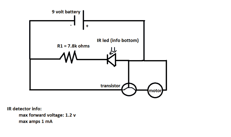
will this work ?
the math i used to determine the resistance of R1 is as follows.
needed voltage drop = 9 - 1.2 = 7.8
r = v/I = 7.8/0.001
r = 7800 ohms
again I am not completely sure that this way of doing it is correct. you can probably tell I am very much a newbie...
also what kinda stuff will i have to consider for the transistor ? like is there a voltage limit ? does it provide considerable Resistance ? will it cause a voltage drop ? will the voltage from the inner circuit be added to it ?
the motor is a 9 v DC motor.
thank you
so i want to be able to run a motor depending on whether or not an IR detector senses IR light. so the basic idea at the start was to connect the motor with the detector and a resistor in series and therefore if there is IR the current will flow turning on the motor. I then learned that the current is limited by the low current device, ie:- the detector.
so will the correct way to go about this be to connect the detector and a transistor in series then connect a motor in parallel and make it depend on the transistor ?
here's a quick diagram of what i mean.
will this work ?
the math i used to determine the resistance of R1 is as follows.
needed voltage drop = 9 - 1.2 = 7.8
r = v/I = 7.8/0.001
r = 7800 ohms
again I am not completely sure that this way of doing it is correct. you can probably tell I am very much a newbie...
also what kinda stuff will i have to consider for the transistor ? like is there a voltage limit ? does it provide considerable Resistance ? will it cause a voltage drop ? will the voltage from the inner circuit be added to it ?
the motor is a 9 v DC motor.
thank you
Attachments

