The Physics of Wheel Movement: Exploring the Dynamics of Torque and Energy

In summary, the conversation is discussing a problem involving a wheel and an armature connected by aluminum struts. The question is why the wheel moves and in which direction. The explanation given involves the change in angle between two points on the armature as the wheel moves, and the force on the aluminum strut. The conversation also mentions using energy principles to solve the problem and reducing the system to four rigid objects. There is also a discussion about the direction in which the flag and point C will move.
  • #1
erensatik
9
3
Homework Statement
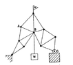
The truss in the figure is made of light aluminum struts freely pivoted at each end. At C is a roller which rolls on a smooth plate. When a workman heats up member AB with a welding torch, it is observed to increase in length by an amount x, and the load W is thereby moved vertically an amount y.
a) Is the motion of W upward or downward?
b) What is the force in the member AB (including the sense, i.e., tension or compression).
Relevant Equations
No relevant equation
Why the wheel moves? I intuitively think that it should move to right but I don't really understand why. When AB gets longer by x each end gets longer by x/2 so W goes to right and down. This will create torque and body will move. This explanation seems valid but I can't calculate anything and you should do it using energy principles.
 

Attachments

  • Screenshot_20211202-175949~2.png
    Screenshot_20211202-175949~2.png
    8.4 KB · Views: 97
Physics news on Phys.org
  • #2
Each triangle of three struts not containing AB is fixed in shape. Can you reduce the system to four rigid objects? Then ask which way the flag moves and hence which way C moves.
 
  • #3
haruspex said:
Each triangle of three struts not containing AB is fixed in shape. Can you reduce the system to four rigid objects? Then ask which way the flag moves and hence which way C moves.
I thought the system is like 4 rod all connected to AB. I don't know this is valid and even if I assume it's true I can't calculate force on AB. Can you make it more clear?
 
  • #4
erensatik said:
I thought the system is like 4 rod all connected to AB.
Yes. Call the joint at the top with the flag F and the other joint adjacent to A and B joint E. If AB lengthens, what happens to angle EBF?
 
  • #5
haruspex said:
Yes. Call the joint at the top with the flag F and the other joint adjacent to A and B joint E. If AB lengthens, what happens to angle EBF?
EBF gets smaller I guess. But I can't solve it. Can you solve it completely?
 
  • #6
erensatik said:
EBF gets smaller I guess. But I can't solve it. Can you solve it completely?
So as angle EBF gets smaller, what happens to the left hand structure that contains segment EB? Does it change its lean angle? Which way?

Similarly, what happens to the right hand structure that contains segment BF? Does it change its lean angle? Which way?

Does W move vertically up or down as a result?
 
  • #7
erensatik said:
I thought the system is like 4 rod all connected to AB. I don't know this is valid and even if I assume it's true I can't calculate force on AB. Can you make it more clear?
Welcome, erensatic! :cool:

I don't see how this problem is related to conservation of energy, other than any geometric change to this armature changes the potential energy of mass W (aluminum struts are light enough as to the weight of the armature not to be considered).

I believe that you don't need to calculate the force on AB, only to conclude the type of load that that aluminum struts is supporting, compression or tension.

If you were to grab points A and B with each of your hands, and then somebody completely removes the AB aluminum strut, what the action of gravity on mass W would force you to do to keep the geometry of the armature as is?

Intuitively, do you believe that your arms would need to restrain points A and B from moving away from each other (hence, AB strut has been under tension load) or to move toward each other (hence, strut has been under compression load)?

You can consider the red and blue portions of the armature as rigid planes.
In that case, and with AB strut removed, the blue plane is free to rotate around the left grounded pivot, while the red plane is free to simultaneously rotate around sliding pivot C.
At the same time, A-Red-plane and A-Blue-plane struts are both free to rotate about their respective pivots.

Armature.png
 
Last edited:
  • Like
Likes erensatik
  • #8
erensatik said:
EBF gets smaller I guess. But I can't solve it. Can you solve it completely?
Model it with two index fingers. Make fists at eye level, facing each other, index fingers extended. Put the tip of the left one half way along the right one (point B). Keep the base of the left finger in a fixed position, and only allow the base of the right to move horizontally.
Which way do you have to move your right hand to reduce the angle the left finger makes to the top half of the right? Does it require moving the fists closer or further apart?
Does B move up, down, or only horizontally?
 
  • Like
Likes erensatik and Lnewqban
  • #9
Thank you all for replying. I think now I can imagine what's going on. A and B would try to move away if you remove AB strut so there is tension and B goes down. I get these. But part b is still a problem. Because answer that the book gives is W(y/x) which is not just tension or compression. I have no idea how to calculate it. Please help.
 
  • #10
erensatik said:
Thank you all for replying. I think now I can imagine what's going on. A and B would try to move away if you remove AB strut so there is tension and B goes down. I get these. But part b is still a problem. Because answer that the book gives is W(y/x) which is not just tension or compression. I have no idea how to calculate it. Please help.
My immediate response was:
"Use conservation of work. If the tension in the strut is T, how much work is need to grow its by length x?"
But I have a doubt about this now. I'll take a closer look later.

Later: ... it's ok, I believe.
 
Last edited:
  • Like
Likes erensatik
  • #11
haruspex said:
My immediate response was:
"Use conservation of work. If the tension in the strut is T, much work is need to grow its by length x?"
But I have a doubt about this now. I'll take a closer look later.
For small displacements, that matches the strategy I had in mind.
 
  • Like
Likes erensatik
  • #12
erensatik said:
... But part b is still a problem. Because answer that the book gives is W(y/x) which is not just tension or compression. I have no idea how to calculate it. Please help.
For any ideal mechanism, input energy (work in) = output energy (work out).
... and work = force times distance.
 
  • Like
Likes erensatik
  • #13
Oh god, I was thinking y as a horizontal movement of W. I kept drawing triangle and used pythagoras for an hour. It's clear now.
I thank everyone for helping me out. By the way, this forum is awesome! Liked it.
 
  • Like
Likes Lnewqban

What is torque and how does it affect wheel movement?

Torque is a measure of the force that causes an object to rotate around an axis. In the context of wheel movement, torque is the force that is applied to the wheel to make it turn. The greater the torque, the faster the wheel will rotate. This is because torque is directly proportional to the angular acceleration of the wheel.

What is the relationship between torque and energy in wheel movement?

Torque and energy are closely related in wheel movement. The energy that is applied to the wheel is converted into torque, which causes the wheel to rotate. The amount of energy that is required to rotate the wheel depends on the amount of torque that is applied and the distance over which it is applied. This relationship is described by the equation E = τθ, where E is energy, τ is torque, and θ is the angle through which the torque is applied.

How does the size and weight of a wheel affect its movement?

The size and weight of a wheel can greatly impact its movement. A larger and heavier wheel will require more torque to turn compared to a smaller and lighter wheel. This is because the larger and heavier wheel has more inertia, which is the resistance to change in motion. Additionally, the distribution of weight on the wheel can also affect its movement, as a wheel with more weight on one side will require more torque to turn.

What are some real-life applications of understanding the physics of wheel movement?

Understanding the physics of wheel movement has many practical applications. For example, it is crucial in designing and optimizing the performance of vehicles, such as cars and bicycles. It is also important in the design of machinery and equipment that use wheels, such as conveyor belts and pulley systems. Additionally, understanding wheel movement can also help in the development of sports equipment, such as wheels for skateboards and rollerblades.

How can we use the principles of torque and energy to improve wheel movement?

By understanding the principles of torque and energy, we can make improvements to wheel movement in various ways. For example, we can optimize the design of wheels to reduce their weight and increase their efficiency. We can also use different materials and technologies to reduce friction and increase the amount of torque that is transferred to the wheel. Additionally, we can apply these principles to develop more efficient and sustainable forms of transportation, such as electric and hybrid vehicles.

Similar threads

  • Introductory Physics Homework Help
Replies
5
Views
883
  • Introductory Physics Homework Help
Replies
13
Views
1K
Replies
7
Views
281
  • Introductory Physics Homework Help
Replies
1
Views
2K
  • Engineering and Comp Sci Homework Help
3
Replies
102
Views
4K
  • Introductory Physics Homework Help
Replies
4
Views
2K
  • Introductory Physics Homework Help
Replies
5
Views
3K
  • Introductory Physics Homework Help
Replies
7
Views
945
  • Introductory Physics Homework Help
Replies
8
Views
1K
  • Set Theory, Logic, Probability, Statistics
Replies
5
Views
278
Back
Top