Calculating the safe load of a glued structure with given shear stress

Click For Summary

Discussion Overview

The discussion revolves around calculating the safe load of a glued structure by analyzing shear stress in a rectangular beam. Participants explore the application of shear stress equations, the location of maximum shear stress, and discrepancies in calculated values compared to given answers.

Discussion Character

  • Technical explanation
  • Mathematical reasoning
  • Debate/contested

Main Points Raised

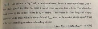
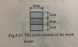
  • One participant attempts to calculate the safe load using the maximum shear stress equation but encounters discrepancies with the expected answer.
  • Another participant questions the location of maximum shear stress on the beam, suggesting it applies at the ends (x=0 and x=l).
  • A participant calculates a value based on the shear stress and beam dimensions but finds it does not match the provided answer, indicating uncertainty about the calculation process.
  • There is a discussion about the shear force acting along the entire beam and the implications for shear stress at different locations.
  • A later reply clarifies that the maximum shear stress applies at y=0, but the provided shear stress is for glued joints at a different location, indicating a misunderstanding in applying the shear stress equation.
  • One participant requests a complete analysis of the beam to further understand the calculations involved.

Areas of Agreement / Disagreement

Participants express differing views on the application of shear stress equations and the locations where maximum shear stress occurs. The discussion remains unresolved regarding the correct approach to calculating the safe load.

Contextual Notes

Participants reference specific equations and values but do not reach a consensus on the correct methodology or assumptions regarding the shear stress and its application in the context of glued structures.

maitake91
Messages
9
Reaction score
4
Homework Statement
A laminated wood beam made up of three 2cm*4cm plates glued together forming a rectangular cross section that is 4cm*6cm is given. The allowable shear stress in the glued joints is 5MPa. The beam is 10cm long and simply supported at both ends.
What is the safe load that can be carried at mid-span and what is the corresponding. maximum bending stress?
Relevant Equations
maximum shear stress in a rectangular beam = 1.5(F/A)
I have tried to calculate the safe load with the equation of maximum shear stress, A = 4*6*10^-4, and the given shear stress 5MPa, but I couldn't seem to get the right answer which is 18kN.
 

Attachments

  • IMG_1282.jpg
    IMG_1282.jpg
    30.5 KB · Views: 184
  • IMG_1283.jpg
    IMG_1283.jpg
    29.3 KB · Views: 167
Physics news on Phys.org
Quote
maximum shear stress in a rectangular beam = 1.5(F/A)

To where on the beam does the maximum shear stress apply?
 
Thank you for your reply!

I think it is at x=0 and x=l, therefore the value F I obtain from the equation is P_max/2?
In that case I'm getting 5*10^6*(4*6*10^-4)*(2/3) = 8000, which is not 9000 as the given answer suggests and I don't know why.
 
  • Like
Likes   Reactions: 256bits
maitake91 said:
Thank you for your reply!

I think it is at x=0 and x=l, therefore the value F I obtain from the equation is P_max/2?
In that case I'm getting 5*10^6*(4*6*10^-4)*(2/3) = 8000, which is not 9000 as the given answer suggests and I don't know why.
For your beam and the related moment and shear force diagrams, shear force acts along the whole beam from 0 to L, with the shear force changing direction at the point of application of the load point P in the centre of the beam.

A shear stress is set up on a face of cross section of the beam in the y-direction. Correspondingly, to make the beam statically in equilibrium, also in the x-direction. For a location y from the central axis, a cube of dimensions dx dy dz would have shear on both opposite faces being equal in magnitude.

For your beam, on this face of cross section, where does the maximum shear stress apply?
 
  • Like
Likes   Reactions: maitake91
256bits said:
For your beam and the related moment and shear force diagrams, shear force acts along the whole beam from 0 to L, with the shear force changing direction at the point of application of the load point P in the centre of the beam.

A shear stress is set up on a face of cross section of the beam in the y-direction. Correspondingly, to make the beam statically in equilibrium, also in the x-direction. For a location y from the central axis, a cube of dimensions dx dy dz would have shear on both opposite faces being equal in magnitude.

For your beam, on this face of cross section, where does the maximum shear stress apply?
Thank you very much, I was able to get the correct answer!

I finally realised that the maximum shear stress applies at y=0, but the shear stress provided is for the glued joints at y = 1cm, therefore I can't just use the equation for maximum shear stress.
 
Let's see your complete analysis of the beam.
 

Similar threads

  • · Replies 2 ·
Replies
2
Views
3K
  • · Replies 4 ·
Replies
4
Views
2K
  • · Replies 6 ·
Replies
6
Views
2K
  • · Replies 6 ·
Replies
6
Views
4K
  • · Replies 1 ·
Replies
1
Views
2K
  • · Replies 4 ·
Replies
4
Views
2K
  • · Replies 1 ·
Replies
1
Views
2K
  • · Replies 4 ·
Replies
4
Views
11K
  • · Replies 6 ·
Replies
6
Views
2K
  • · Replies 8 ·
Replies
8
Views
4K