Equilibrium Conditions for a Rotating Rod with Two Point Masses

19 replies · 4K views · last reply
Amitayas Banerjee
Messages
31
Reaction score
2
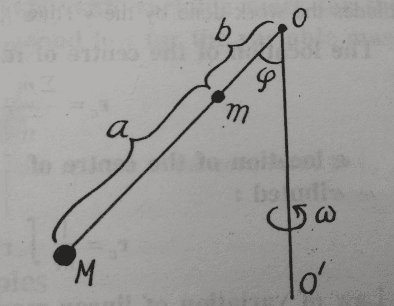
1. A weightless rod carries towards of masses M and M. The roads Hinge Joint to vertical axis OO', which rotates with an angular velocity ω. Determine the angle φ formed by the rod and there vertical.
WhatsApp%20Image%202018-08-19%20at%209.41.06%20AM.jpeg


Diagram of a rod pivoted at point O on a vertical axis OO' rotating with angular velocity ω, with masses M and m on the rod at distances a and b from O and angle φ between the rod and the axis.

The attempt at a solution

If I am not wrong, the two ways to ensure equilibrium are ensuring net force=0, or net torque=0.

i) Net force=0:
The center of mass of the system will be at a distance $$\frac{Ma}{m+M}$$ from mass m between M and m.
Therefore the F=ma eqn. perpendicular to the rod for the imaginary mass (m+M) seems to be
Typeset equations: (m+M)ω²(Ma/(m+M) + b) sin φ cos φ = (m+M)g sin φ; then ⇒ φ = cos⁻¹( (mb + M(a+b))/(m+M) · g/ω² ); then 'or' φ = 0.


Now, the second ans, φ=0, is given in the book in the ans section, but the first ans is wrong.
If we start balancing the torque, then this eqn. comes again as the distance between the hing and the point of actions of the centrifugal forces are same.
Printed answer from a textbook: φ = 0, cos⁻¹( (mb + M(a + b)) / (mb² + M(a + b)²) · g/ω² )

Above is the answer given in the book.
 
Attachments
  • Diagram of a rod pivoted at point O on a vertical axis OO' rotating with angular velocity ω, with masses M and m on the rod at distances a and b from O and angle φ between the rod and the axis.
    upload_2018-8-19_13-7-41.png
    78.5 KB · Views: 661
  • Typeset equations: (m+M)ω²(Ma/(m+M) + b) sin φ cos φ = (m+M)g sin φ; then ⇒ φ = cos⁻¹( (mb + M(a+b))/(m+M) · g/ω² ); then 'or' φ = 0.
    upload_2018-8-19_13-13-2.png
    33.7 KB · Views: 658
  • Printed answer from a textbook: φ = 0, cos⁻¹( (mb + M(a + b)) / (mb² + M(a + b)²) · g/ω² )
    upload_2018-8-19_13-14-33.png
    22.2 KB · Views: 676
You can't replace the two forces by the force the sum of the masses at the center of mass would experience. The force is not linear with distance.
 
Would you please explain which two forces are you talking about? The centrifugal or the weight? And what is meant by forces not being linear with distance?
 
Ah my mistake, as they rotate in a fixed arrangement it will work in this case.

How did you set up your equation? As far as I can see you set forces equal that go in different directions. There will be a net force on the support. Only torque balance gives you a condition for the equilibrium.
Also note that your answer has inconsistent units, you can only take the inverse cosine of a number without units. That is always a certain sign that something is wrong (but here it was from an unrelated mathematics error).
 
  • Like
Likes   Reactions: Amitayas Banerjee
Handwritten sketch of two point masses M and m on a line tilted at angle φ from a vertical rod, with distances a and b marked, and an arrow labeled Ma/(m+M) pointing to an imaginary mass (m+M) at the center of mass.

Below is the FBD for the imaginary mass:
Handwritten free-body diagram of a point mass on a rotating rod, with a dot at the mass and arrows labelled (m+M)ω₀²r cosφ pointing up-left, mg sinφ pointing down-right, and r pointing along the rod; a curved line links the dot to a label (m+M) at bottom left.

According to me, the value of r is [Ma/(m+M)] + b
Now, please explain me why this will not work.
Sorry, there is a small error in the second image... the force mgsinφ should be (m+M)gsinφ
 
Attachments
  • Handwritten sketch of two point masses M and m on a line tilted at angle φ from a vertical rod, with distances a and b marked, and an arrow labeled Ma/(m+M) pointing to an imaginary mass (m+M) at the center of mass.
    upload_2018-8-19_15-2-13.png
    56.7 KB · Views: 670
  • Handwritten free-body diagram of a point mass on a rotating rod, with a dot at the mass and arrows labelled (m+M)ω₀²r cosφ pointing up-left, mg sinφ pointing down-right, and r pointing along the rod; a curved line links the dot to a label (m+M) at bottom left.
    upload_2018-8-19_15-3-3.png
    80.5 KB · Views: 587
These are not the directions of forces. And while you could combine the two masses to one to consider forces, you can't do it for torque. You'll have to consider the masses separately.
 
I agree with you that balancing the torques will give an equilibrium condition. Also, I have reached the correct ans by balancing the torques. But will also balancing forces on the COM not give an equilibrium condition?
 
Last edited:
Amitayas Banerjee said:
If I am not wrong, the two ways to ensure equilibrium are ensuring net force=0, or net torque=0.
You are wrong. Equilibrium requires that both forces and torques balance. Depending on what is known and how you choose your axes and force component directions you can sometimes avoid writing the full set of such equations.
In the present problem, you have an unknown force, with two degrees of freedom, at the hinge. Together with the angle to be found, that makes three unknowns. This means that only writing the two linear force balance equations will not allow you to solve the problem. You can combine these with a torque equation using whatever axis you like... CoM is fine.
Alternatively, by taking the axis at the hinge you can avoid involving those two unknowns and solve the problem with a torque equation alone.
 
  • Like
Likes   Reactions: mfb
Hand-drawn diagram of a rigid rod with two point masses labelled m on either side of a centre of mass marked COM, pivoting at a hinge with angle phi, and a perpendicular axis labelled alpha axis.

I have marked both the masses along with the center of mass of the rod. α axis is an axis defined by me as shown in the diagram. It is perpendicular to the rod.
Now, my question is, if we balance the forces on the COM along the axis and ensure that there is no movement of the COM along the α axis, then does this not imply and is implied by the fact that the rod will not rotate about the hinge?
 
Attachments
  • Hand-drawn diagram of a rigid rod with two point masses labelled m on either side of a centre of mass marked COM, pivoting at a hinge with angle phi, and a perpendicular axis labelled alpha axis.
    upload_2018-8-20_15-20-40.png
    47.7 KB · Views: 552
Amitayas Banerjee said:
It is perpendicular to the rod.
That doesn't quite define it. If it is perpendicular to the rod but in the plane containing the rod and the rod's axis of rotation then it is of no relevance. All the forces will pass through that axis (or be parallel to it) and so have no moment about it.
When I wrote post #8 I was thinking of it as essentially a two dimensional problem, which it is. All the forces are in one plane and all the torques are therefore about axes normal to that plane. So when I wrote "any axis will do", I meant any axis normal to the plane.

If your α axis is indeed intended normal to the plane then I do not understand your later remarks. There are no forces along such an axis.
 
I did not write my post #9 based on your #8. My α axis is on the plane and not normal to it and perpendicular to the rod. And I balance forces along this axis on the COM.
 
Amitayas Banerjee said:
I did not write my post #9 based on your #8. My α axis is on the plane and not normal to it and perpendicular to the rod. And I balance forces along this axis on the COM.
In that case, my response to post #9 is that those forces will include an unknown force from the hinge, so does not allow you to deduce the angle without further equations. And as I showed in post #8, at least one equations will have to be a torque equation.
 
What is meant by unknown force from hinge? And why will it not be there while considering torque?
 
Amitayas Banerjee said:
What is meant by unknown force from hinge?
The rod is supported and restrained by the vertical axle. That axle must exert a vertically upward force on the rod to prevent its sliding down, and a horizontal force to prevent its flying away from the axle. No matter which direction you choose to resolve forces along, one or both of these will feature in your equation, and you do not have independent way to determne either.
Amitayas Banerjee said:
why will it not be there while considering torque?
If you take moments about an axis that passes through the line of action of a force then that force has no moment about the axis, so can be ignored.
See the Tip in section 1 of https://www.physicsforums.com/insights/frequently-made-errors-mechanics-moments/
 
Hand-drawn diagram of a rigid rod hanging from a pivot at its upper right end, with a string drawn from the pivot to a short vertical line below. A point mass labelled m sits on the rod near its middle, and a larger mass labelled M hangs at the lower left end. An arrow above the rod is labelled string.

This is a new system.

All things are same, only in this case, the rod is attached to an ideal string with very small length.

Here, the tension acts on the rod parallel to it(along it, to be more specific). So, no force acts along the α axis, and my math works here, does it not?
 
Attachments
  • Hand-drawn diagram of a rigid rod hanging from a pivot at its upper right end, with a string drawn from the pivot to a short vertical line below. A point mass labelled m sits on the rod near its middle, and a larger mass labelled M hangs at the lower left end. An arrow above the rod is labelled string.
    upload_2018-8-20_17-1-28.png
    63.7 KB · Views: 674
Amitayas Banerjee said:
Here, the tension acts on the rod parallel to it(along it, to be more specific).
You are assuming the rod and string would lie in a straight line. That needs to be proved.
 
haruspex said:
You are assuming the rod and string would lie in a straight line. That needs to be proved.
You can't prove something that is not true.
 
haruspex said:
In that case, my response to post #9 is that those forces will include an unknown force from the hinge, so does not allow you to deduce the angle without further equations. And as I showed in post #8, at least one equations will have to be a torque equation.
But, will this force not be balanced by the weight of the rod? Can you show me the correct FBD of the rod?
 
Last edited:
Amitayas Banerjee said:
But, will this force not be balanced by the weight of the rod? Can you show me the correct FBD of the rod?
In the rotating frame, you have the two weights, the two centrifugal forces and, at the hinge, an unknown horizontal force and an unknown vertical force.